SPARK is an annotated sub-language of Ada with a number of properties making it uniquely suitable for the development of critical systems. The complete avoidance of ambiguity in SPARK, and the accuracy of expression that this allows, makes it possible to reason about SPARK programs in precise ways. The ability to reason is essential if we are to be able to construct an argument that a system will be fit to perform a highly-critical function prior to the existence of any in-service experience. The ability to reason early is our only defence against the proven high cost of detecting errors late on in the software development process (e.g. during test and, especially integration test).
Experience with SPARK demonstrates its suitability for the cost-effective implementation of critical systems; however, it has also shown that SPARK makes special demands on the design of systems if the full benefits are to be realised. Although SPARK is a true subset of Ada it is a mistake to assume that any Ada-compatible design approach can be used unchanged with SPARK. The main reason for this is that SPARK’s annotations, which are essential to give SPARK its desirable property of precision, reveal qualities of the software which are often wrongly and too easily ignored. For example, SPARK’s “own variable” annotation reveals the presence of state within a package and the “derives” annotation reveals interactions and coupling between elements of system state. SPARK’s annotations ruthlessly reveal failures to achieve desirable design properties such as loose coupling between units and adequate abstractions of data. Such deficiencies are a prime cause of project failures, especially in large projects where the complexity is often of the order of the square of the number of data items being controlled. Annotation tractability can therefore be seen as measure of design “quality”. The design method outlined below seeks to exploit this measure by producing a design where minimising the flow of information between subsystems is a prime objective. Resultant designs should exhibit those properties known to be desirable, such as high cohesion and loose coupling, and will therefore be “SPARK-friendly”. The methods also seek to produce design abstractions, partial designs and designs which can be analysed very early by the Examiner; this makes iterative design changes easier to manage and avoids unpleasant surprises late in the development process.
The methods described are general but are biased towards embedded, critical control functions since this is the application area where SPARK is most likely to be employed. The general methods can readily be instantiated using design notations such as HOOD and UML. A basic knowledge of SPARK is assumed, perhaps from attending Praxis’ 4-day “Software Engineering with SPARK” course or from reading “High Integrity Software: The SPARK Approach to Safety and Security” [1].
The name of the method is loosely derived from the concept of using information flow as a central tool in the design of the objects or entities making up the system. INFORMED is an INformation Flow ORiented MEthod of (object) Design.
The approach remains applicable even if derives annotations are not provided in the SPARK source code and information flow analysis is not being performed by the Examiner. In this case the global annotation will provide some indication of the strength of coupling between objects and the need for unexpected modes on globals (e.g. mode in out on global state that appears logically to be an input) is the indicator of unnatural information flows.
The rest of this document describes the design process in increasing levels of detail. An overview, abstract view of the design process is covered in Section 2, which also identifies the desirable properties of good designs. Section 3 describes the basic building blocks or templates that can be assembled into an INFORMED design. Section 4 details the design steps necessary to select which building blocks to employ and how best to use them.
Section 6 introduces four case studies which are intended to illustrate various facets of the INFORMED approach and describes a simple notation that is used in them. The case studies themselves follow in Sections 7 to 10.
Following some concluding remarks, are three appendices dealing with some specific design aspects involving initialization of system state and handling the needs of specific forms of testing and data logging.
Software design is a creative process that depends for its success on the talent, experience and effort of the designer. It is no more possible to establish a formulaic approach to design, guaranteed to bring success, than to provide a mechanism guaranteed to produce a great painting or perfectly-formed jazz solo[1]. Nevertheless the properties of a good design are reasonably well understood and it is possible to outline approaches to design that are likely to bring success (or at least avoid known causes of failure). Crucially, however, design must be an iterative process that considers multiple levels of abstraction simultaneously and continually measures the steps proposed against the desired goals. Furthermore, the applications of several design techniques are likely to be necessary to bring success.
Sadly the innate creativity of design does not seem to be universally recognised and far too many methods are promoted, with messianic zeal, as panaceas. Perhaps the approaches most prone to such hype are the objected-oriented design (OOD) methods, discussion of which is greatly complicated by its confusion with specific languages and language features intended to support object-oriented programming (OOP). Some of these methods even go as far as claiming that the software design process does not even exist in the belief that the design emerges as a free by-product of the requirements capture phase.
The INFORMED design approach makes extensive use of OOD techniques but does not require the more dynamic OOP techniques such as message passing and dynamic dispatch. Such techniques are, in any case, inappropriate for critical systems since they deny us the ability to reason statically about system behaviour, defy current verification techniques and place undue burden on dynamic testing. We focus on the heavily interconnected properties associated with OOD that are described below. A good design will strike a balance between these various characteristics and extremes should be treated with suspicion. For example a design which placed the entire program in a single procedure might score well on encapsulation but would be very poor when measured for cohesion!
Encapsulation is the clear separation of specification from implementation; this is sometimes described as a “contract model” of programming. It is an important principle that users of an object should not be concerned with its internal behaviour. Were this not the case then loose coupling could not be achieved. The principle of encapsulation applies not only to data and operations but even to type declarations: for example, a limited private type provides more encapsulation than a concrete Ada type declaration.
Abstraction is a necessary component of encapsulation. Abstraction allows us to strip away (ignore) certain levels of detail when taking an external view of an object; the detail is hidden by being encapsulated in the object. The term “information hiding” is frequently used in this context. This term is somewhat inappropriate for critical systems about which reasoning is important: information, by definition, informs. We cannot reason in the absence of information; however, we can ensure that our reasoning takes place at an appropriate level of abstraction, which we achieve by hiding detail. Hiding unnecessary detail allows us to focus on the essential properties of an object. The essential properties are those which support encapsulation by allowing use of an object without the need to be concerned with it implementation. SPARK annotations, particularly the own variable clause, which reveals the presence of “state” in a package, are essential in this respect. Without annotations to strengthen the specification of an object, safe use would require inspection of the implementation and would break the contract model encouraged by encapsulation.
Coupling is a measure of the connections between objects. Highly coupled objects interact in ways that make their separate modification difficult. Undesirable, high levels of coupling arise when abstractions are poor and encapsulation inadequate.
Software components can be strongly or weakly coupled. The OOD literature is not entirely consistent as to which forms of coupling are weak and which are strong and therefore less desirable. SPARK provides a simple and clear distinction: the appearance of a package name only as a prefix in an inherits annotation represents weak coupling (use of a service) but its appearance in a global or derives annotation indicates strong coupling (sharing of data).
Where excessive coupling results from inadequate data abstraction it will be revealed by the size and complexity SPARK’s derives and globals annotations: the goal of optimising information flow is therefore equivalent to achieving loose coupling. Excessive coupling is most evident when derives annotations are used and information flow analysis conducted. Global annotations provide a less sensitive, but still effective, indication of coupling for programs being subjected only to data flow analysis.
Whereas coupling is measured between objects, cohesion is a property of an object. Cohesion is a measure of focus or singleness of purpose. For example, a car has both door handles and pistons but we would not expect to find both represented by a single software object. If they were, we would not have high cohesion and modifying the software to support a 2-door rather than 4-door model (or to replace a straight 4 with a V8 engine) would involve changing rather unexpected parts of the design. There is a clear distinction between the isolation provided by highly-cohesive objects and the need to arrange such objects in hierarchies as described below.
The principles of cohesion apply also to (concrete) type declarations, especially since in Ada, a type declaration also implicitly declares a set of operation functions for that type. The section below on type packages illustrates this point.
Here we recognise that in the real-world objects exhibit hierarchy. Certain objects are contained inside others and cannot be reached directly. When we approach a car we can grasp a door handle but not a piston: the latter is inside the engine object which is itself inside the car. Many OOD methods are prone to producing unduly flat networks of objects (that would make door handles and pistons of equal prominence) which can easily encourage extra, undesirable, coupling between objects. In some cases, the old spaghetti code of gotos that structured programming eliminated, re-emerges as spaghetti-in-the-large with Byzantine control flow between vast rafts of objects; this is sometimes called “spaghetti inheritance”. Establishing a clear object hierarchy, encouraged and checked by the rules of SPARK, minimises this effect and contributes to the goal of keeping the flow of information under control — loose coupling. Hierarchy also exists in the abstractions we use: sometimes we will want to think of our car in the abstract, complete sense. Sometimes we will be interested in the properties of the engine and sometimes in the qualities of a piston within the engine. All these properties are properties of the car but they can be viewed in a hierarchy of levels of abstraction with different details hidden at each different level.
Another view of hierarchy, which is mainly concerned with inheritance of object properties, is common in the OOD literature but rather less relevant to INFORMED. This view, continuing the car analogy, would place great emphasis on a car being an example of a “land vehicle” which is itself an example of a “means of transport”; however, it would not ensure that the object hierarchy described above was enforced.
3 Basic Design Elements of INFORMED
The INFORMED method uses elements of both object oriented and functional design. OOD is used to establish the architecture of the system and the elements of system state it contains. The result is an annotated framework of SPARK packages that can be analysed at an early stage using the Examiner.
Implementation of the functional elements of objects is best achieved by a classic top-down refinement process. SPARK annotations, supported by the Examiner, can check that the desired properties of the design are being maintained.
Inspection of many designs and systems shows that certain key building blocks, or templates, are used repeatedly. Design can be simplified by making use of such building blocks and concentrating on how they should be fitted together; this is similar to building construction using prefabricated components rather than building brick by brick. INFORMED designs can be implemented using just three key building blocks, which are:
· main programs;
· variable packages; and
· type packages.
A main program[2] is the top-level, entry point controlling the behaviour a system or sub-system. Typically the SPARK implementation of an INFORMED design will have only one such main program (annotated with SPARK’s main_program annotation); however, it is possible to a build system where each scheduled thread is regarded as a main program with the scheduling taking place outside the SPARK system boundary.
Main programs have the following general form:
with A, B, C;
--# inherit A, B, C, D;
--# main_program;
procedure Main
--# global in out A.State, B.State, ...
--# derives ...
is
procedure Initialize;
....
begin -- Main
Initialize;
loop
ControlProcedure;
end loop;
end Main;
For anything other than very small systems, the control procedure is likely to be decomposed into several smaller procedures. A useful aim here is to make each such decomposed procedure responsible for a single “mode” of the system’s behaviour. For example, in the cycle computer case study described in Section 10, there are separate modes for programming the unit with the size of the bicycle’s wheel and for normal operation. Handling these modes in separate procedures supports the aim of cohesion and will help generate clear and useful annotations for each operation.
Sometimes SPARK programs do not to have a main program at all. In these cases top-level control is provided by some scheduler that is either custom written or provided by the operating system. In these cases a main program might be used as a substitute for the scheduler for analysis purposes. Even where a main program is not used, it is important to consider what form it might take if it did exist; this is because an important part of the INFORMED process is to consider what effect alternative design decisions would have on annotations at the main program level.
A variable package is a SPARK package that contains static data or “state” as revealed by an own variable annotation. For most practical purposes a variable package is equivalent to what is nowadays called an object. It is also synonymous with what used to be called an abstract state machine. The name variable package is intended to emphasise the characteristics of such packages which, with one important distinction discussed later, behave exactly like variables. When we write:
X : Integer;
in a SPARK program we are naming a container (X) which can contain values of a certain shape (Integers) upon which certain operations are possible (+, - etc.).
Similarly when we write:
package Stack
--# own State;
is
procedure Clear;
--# global out State;
--# derives State from ;
procedure Push(X : in Integer);
--# global in out State;
--# derives State from State, X;
procedure Pop(X : out Integer);
--# global in out State;
--# derives X, State from State;
end Stack;
we are defining a container (Stack.State) that can contain values of a certain shape (“abstract stack”) upon which certain operations can be performed (Clear, Push, Pop). There is clearly a direct equivalence between the two declarations. Furthermore, a library-level variable package behaves like a global variable and an embedded package like a local variable. The term “variable package” helps reinforce this equivalence. The only difference between an variable package and a variable declared using normal Ada syntax is that the former cannot be passed as a parameter whereas the latter can; this can have a significant effect as revealed by the tiny compiler case study at Section 9.
SPARK’s own variable annotation gives us a name for the state contained in the variable package that we can use in annotations to clarify our intended use of it. Encapsulation and abstraction can be maintained because no details of the internal structure of the state need be revealed. Hierarchy is facilitated because SPARK refinement rules allow a package’s abstract state, as named in its own variable clause, to represent a number of more detailed state items which are conceptually inside the object. Thus a car object could contain an engine object which might contain a number of piston objects. The abstract own variable at the car-level of abstraction represents the agglomeration of all the state of the enclosed objects. At the most concrete level will be a number of Ada primitive objects. SPARK 95 private child packages allow the logical nesting or embedding of variable packages without the need physically to embed the packages that represent them.
A type package is also a SPARK package although in this case the package does not have state and therefore does not require an own variable annotation.
Instead a type package exports the name of a type (or types) which may be a concrete Ada type, a private type or a limited private type. For private (abstract) types the package will also provide a set of operations that may be performed on objects of that type. Declaration of a concrete Ada type implicitly declares a set of operations although these might be extended by declaration of further operations in the type package.
Type packages perform the same function — the declaration of a template from which objects can later be formed — regardless of whether they export concrete, private or limited private types. The level of abstraction and encapsulation increases in with each step along this list but the fundamental purpose and behaviour of the package does not. Indeed, during initial design stages it may be unclear whether a type should be implemented in abstract or concrete form. A type package is essentially equivalent to what is now often called a class and was formerly known as an abstract data type.
Variables of the types declared in type packages can be declared at the point of use and passed as parameters to the operations provided. Because this facilitates localization of state, type packages are a very powerful mechanism for the reduction of information flow, and hence coupling, in systems. In this document the term “instance of a type package” means the declaration of a variable of a type declared in and exported by the type package.
3.3.1 Type Packages Declaring Abstract Types
The stack variable package presented earlier can be restructured as a type package declaring an abstract type as follows:
package Stack
is
type T is private;
procedure Clear(S : out T);
--# derives S from ;
procedure Push(S : in out T;
X : in Integer);
--# derives S from S, X;
procedure Pop(S : in out T;
X : out Integer);
--# derives X, S from S;
private
--# hide Stack;
-- full Ada declaration of type T would go here
end Stack;
Like variable packages, type packages can exhibit hierarchy because a type package might be implemented as a record containing fields that are of other type packages.
The declaration of a variable of this type package would look like this:
MyStack : Stacks.T;
It is often useful if a type package exports a deferred constant giving a safe and useful value that can be used to initialize variables of that type. For example:
MyStack : Stacks.T := Stacks.Empty;
This approach can be useful when variables of a type package form refinement constituents of a SPARK abstract own variable which appears in its package’s initializes annotation; however, the use of deferred constants in this way does make it impossible to make such a type “limited”. It is worth noting here that some of the reasons for using limited in full Ada do not apply in SPARK and that generally private types in SPARK provide as much abstraction and encapsulation as is likely to be needed. Only in very special circumstances where it is essential to prohibit copying of a variable is the extra protection provided by limited worthwhile.
3.3.2 Type Packages Declaring Concrete Types
Type packages declaring concrete types or subtypes are required when visibility of a type declaration must be shared by other design elements. The need for and scope of such types should be assessed against the design principles outlined above. For example, if a boundary variable (see Section 3.5) returned the position of a switch (which might be on, off or unknown) then the considerations of cohesion would suggest that no type package was needed because a SPARK enumerated type declaration suitable for representing the switch could form part of the boundary variable itself. If more than one boundary variable was concerned with monitoring switches they would all need to see the (on, off, unknown) enumerated type declaration. We could choose to place the declaration in one of the switch-monitoring boundary variables and have the others obtain it from there; however, this would introduce a false hierarchy into the system making one of the switches “more important” than the others. Instead a type package declaring the enumerated type, which can be shared by all the boundary variables is clearly appropriate. This also introduces an appropriate form of hierarchy because we have a declaration of a general switch type which is used by boundary variables representing a set of specific switches. The principle of cohesion may also suggest that the switch type declaration is not mixed with other type declarations (e.g. airspeed, or valve position); this has very beneficial effects on naming conventions. For example, if we have two type packages to represent, respectively, a switch position and a valve position:
package Switch is
type T is (On, Off, Unknown);
end Switch;
package Valve is
type T is (Open, Closed, Unknown);
end Valve;
we can readily declare variables Y : Switch.T and X : Valve.T and test conditions such as if X = Valve.Open and Y = Switch.Off; this is clearly superior to breaking cohesion by lumping the declarations together:
package BasicTypes is
type SwitchType is (On, Off, Unknown);
type ValveType is (Open, Closed, Unknown);
end BasicTypes;
leading to Y : BasicTypes.SwitchType; X : BasicTypes.ValveType and if X = BasicTypes.Open and Y = BasicTypes.Off. The second solution also presents a problem with the illegal (in SPARK) overloading in a single scope of the enumeration literal Unknown.
The introduction of child packages, especially in this case public children, to SPARK 95 provides a useful method of making these kinds of declaration in a hierarchical form which also provides consistent and meaningful naming. For example:
package Discretes
is
-- entry point for the package hierarchy only
end Discretes;
package Discretes.Valve
is
type T is (Open, Shut, Unknown);
end Discretes.Valve;
package Discretes.Valve.Butterfly
is
type T is (Open, Shut, Unknown);
end Discretes.Valve.Butterfly;
package Discretes.Switch
is
type T is (On, Off, Unknown);
end Discretes.Switch;
Although the main components of an INFORMED design are those described above there is sometimes the need for additional packages to provide shared services to them. Such utility packages never contain state variables (otherwise they would be variable packages) and do not declare types (otherwise they would be type packages). Utility packages are nowadays sometimes called “Class Utilities”.
The need for utility packages arises when an operation is required which affects or uses more than one variable package or type package and which it would not be appropriate to consider part of one or another. Given type packages representing “man” and “woman” the operation “marry” should probably operate on one of each and would therefore need to be an utility package. Placing the marry operation in either the man or woman type package would suggest a false hierarchy and certainly be politically incorrect!
Care should be taken to prevent the proliferation of utility packages. In many cases the correct place for an operation is in one of the type packages or variable packages on which it operates. For example, given a type package representing a FIFO queue and another representing a LIFO stack it would be easy to provide a “reverse queue” operation in a utility package that took a queue as one parameter, a stack as another and reversed the queue by pushing it onto the stack and popping it back into the queue. This would not be a good design decomposition because the operation “reverse queue” clearly applies only to the abstract queue type and the stack is used only to perform the operation. The reverse queue operation should therefore be part of the queue type package which will declare a local stack in which to perform the reversal. This increase in cohesion will also make it simpler to show that the stack is of adequate size to reverse any queue that may be declared.
Boundary variables are particular kinds of variable package which provide interfaces between the software functionality described by the INFORMED design and elements outside it with which it must communicate. All communication across this system boundary is via boundary variables. Boundary variables provide an abstraction of communication and model the inherent concurrency associated with such communication. The entity with which the SPARK program communicates might be some kind of hardware sensor or actuator; or an “API” of some library or co-operating software system.
A boundary variable is a variable package; however, unlike other instances of such variables the name provided in its own variable clause is a place holder representing the stream of data arriving from, or being sent to, the outside world rather than simply an abstract name for the internal state of the package. The package may have some internal state as well but what distinguishes a boundary variable is that at least a part of the state represented by its own variable clause is connected to the environment in some way.
The inherent concurrency involved in reading a sensor occurs because some external (perhaps physical rather than computational) process modifies the value read by the sensor in ways that are not under the control of the software. For example, a lift controller reacts to lift users pressing buttons; however, the users are not controlled by the software and every time the software inspects the buttons the values found may be different depending on the concurrent behaviour of the users. Similar issues occur in system-level outputs. Successive writes to a variable, without any intervening reads, are usually regarded as “ineffective”; however, if the variable is a memory-mapped system level output then there may well be a significant effect, outside the program boundary, from the writes.
System boundaries must be formed by boundary variables. Because of the need to use an external own variable as a model of input/output communication it is not possible to use type packages to provide such interfaces.
SPARK provides several mechanisms for describing and implementing boundary variables. These are discussed in more detail in Appendix A.
3.5.1 Boundary Variable Abstraction Layers
It is often useful to place an abstraction layer between the boundary variables of a system and their users; this approach is appropriate where direct use of the boundary variables would provide insufficient abstraction allowing too much detail to become visible in higher level SPARK annotations.
Boundary variable abstractions exploit SPARK’s refinement mechanism and use a SPARK package to provide indirect access to the boundary variables it is abstracting. These, lower-level, boundary variables are either embedded in the abstraction layer (SPARK 83 or SPARK 95) or are private children of it (SPARK 95 only). The abstraction may hide the fact that more than one boundary variable is involved in providing the abstract inputs or may hide some other processing such as calibration that is taking place.
The example given below is obtained from the cycle computer example described in Section 10 and provides an abstraction of two specific control buttons, Reset and Mode, such that they both now are regarded as being obtained from a single external source called Controls.State. The abstraction is achieved by use of private child packages.
package Controls
--# own in State;
is
type Buttons is (Pressed, NotPressed);
procedure ReadReset(Setting : out Buttons);
--# global in State;
--# derives Setting from State;
procedure ReadMode(Setting : out Buttons);
--# global in State;
--# derives Setting from State;
end Controls;
--# inherit Controls;
private package Controls.Reset
--# own in State;
is
procedure Read(Setting : out Controls.Buttons);
--# global in State;
--# derives Setting from State;
end Controls.Reset;
--# inherit Controls;
private package Controls.Mode
--# own in State;
is
procedure Read(Setting : out Controls.Buttons);
--# global in State;
--# derives Setting from State;
end Controls.Mode;
with Controls.Reset, Controls.Mode;
package body Controls
--# own State is in Controls.Reset.State,
--# in Controls.Mode.State;
is
procedure ReadReset(Setting : out Buttons)
--# global in Reset.State;
--# derives Setting from Reset.State;
is
begin
Reset.Read(Setting);
end ReadReset;
procedure ReadMode(Setting : out Buttons)
--# global in Mode.State;
--# derives Setting from Mode.State;
is
begin
Mode.Read(Setting);
end ReadMode;
end Controls;
Often the creation of a boundary variable abstraction layer occurs from reasoning in the opposite direction to that described above, where we chose to insert a layer to provide an abstraction of two boundary variables. Instead we may have chosen a boundary variable to represent some logically significant input value and then found that it can be implemented in terms of more detailed, embedded, boundary variables. In this case we turn the package previously identified as a boundary variable into a boundary abstraction layer and refine it into one or more boundary variables (and perhaps some other processing code). This process is illustrated in the room temperature control case study at Section 8.
It should be no surprise that we sometimes see the use of abstraction layers in terms of abstractions and sometimes in terms of refinements since these are reciprocal processes or two sides of the same coin.
The balance between abstraction and refinement also occurs in the selection of the SPARK boundary of the system. For example, we might wish to provide abstract names for entities that are all obtained from a single concrete Ada source; this is discussed in Section 5.1.
A very important rule concerning boundary variable abstractions is never to mix input and output boundary variables in a single abstraction; this invariably leads to confusing and misleading information flow results where inputs incorrectly appear to depend on values previously sent as outputs.
4 Principles of the INFORMED Design Approach
The design steps outlined below are based on the following principles:
· application-oriented annotations;
· minimised information flow;
· clear separation of the essential from the inessential;
· careful selection of the SPARK implementation boundary; and
· early use of static analysis.
The following sections describe these in more detail.
4.1 Application-oriented Annotations
SPARK annotations provide an expression of the behaviour of the system in parallel with the code itself. This description is most useful if it is expressed in problem domain terms rather than in implementation terms. For example we might prefer to see annotations in terms of “master switch” and “thermostat” rather than “register A” or “analogue to digital converter 2”.
To reason about the behaviour of the software we will inevitably have to reason about the information that flows round it. This reasoning is simplified if the information that flows is the minimum that is necessary for the software to perform its task. Unnecessary “pumping” of data from one part of the system to another will increase the complexity of the information flows as revealed by SPARK’s annotations. Methods for minimising information flow include:
· minimising propagation of unnecessary detail;
· localisation and encapsulation of state;
· avoiding making copies of data; and
· appropriate use of hierarchy.
These are considered in more detail in Section 5.
4.3 Clear Separation of the Essential from the Inessential
Software designers have to reconcile many, sometimes conflicting, constraints. For example, good design might dictate that data is localised and encapsulated; however, the need to monitor data during rig testing of a system might require that data to be placed instead in some global location. An important principle of INFORMED is that the dictates of good software engineering, and providing the core functionality of the system in the most elegant way possible, must take priority. This does not mean that other peripheral needs are not addressed but that they should not be addressed in ways that unnecessarily distort the basic design. In the example given above, the data should not be made global just for test purposes because this is distorting the design for secondary reasons. The data should be located in the optimum place to ensure minimal information flow and then steps taken to make it accessible to the test team using additional code clearly identified, by flow analysis, as not being necessary for the core functionality of the system.
4.4 Careful Selection of the SPARK Implementation Boundary
The above principles are facilitated if careful thought is given to where the boundary of the SPARK system (i.e. those parts of the system that will be seen by the Examiner) lies within the overall system boundary. It is not necessarily the case that everything that could be included in the SPARK system should be. For example, the goal of providing annotations in application domain terms may require selection of boundary variables that are higher-level and more abstract than the most fine-grained that could be expressed in SPARK. There are also situations in which the best implementation might consist of more than one SPARK system within the overall system boundary. These issues are considered further in the detailed description of the design steps and the case studies that follow.
4.5 Early use of Static Analysis
The design should be submitted to the Examiner as early as possible and the analysis process should continue as it evolves. The use of the Examiner in this way constantly checks the design choices that are being made and makes a major contribution to ensuring that the design aims are met. Early use of the Examiner is facilitated by the use of abstraction, by deferring implementation decisions, and by use of the Examiner’s “hide” directive.
Although the following steps are provided in the form of a list or sequence there is considerable looping, backtracking and feedback required in practice. The general process is to postulate a solution to each design step and then test it by trying to proceed to the next. If a step is difficult to perform then it is possible that an inappropriate choice was made at some earlier step. The detailed descriptions of the design steps that follow suggest where iteration is most likely. The overall process is one of moving from the abstract to the concrete. Within that movement it is likely that various major system sub-components will be identified each of which can have the INFORMED process applied to it in turn.
The design steps, and some of the activities they encompass, are as follows:
1 Identification of the system boundary, inputs and outputs.
· Identify the boundary of the system for which INFORMED is being used to provide the software.
· Identify the physical inputs and outputs of the system.
2 Identification of the SPARK boundary.
· Select a SPARK boundary within the overall system boundary; this defines the parts of the system that will be modelled and coded in SPARK and which will be subject to analysis by the SPARK tools.
· Define boundary variables to give controlled interfaces across the SPARK boundary annotated in problem domain terms. This step is tightly bound and iterative with the previous bullet.
· Consider adding boundary abstraction layers.
3 Identification and localization of system state.
· Identify the essential state of the system; what must be stored?
· Decide in what terms we wish the annotation of the main program to be expressed. Any state outside the main program will appear in its annotations, any inside will not.
· Using these considerations, assess where state should be located and whether it should be implemented as variable packages or instances of type packages.
· Identify any natural state hierarchies and use SPARK refinement to model them. Introduce utility layers where appropriate.
· Test to see if the resulting provisional design is a loop-free partial ordering of packages and produces a logical and minimal flow of information. Backtrack as necessary.
4 Handling initialization of state.
· Consider how state will be initialized. Does this affect the location choices made?
· Examine and flow analyse the system framework.
5 Handling secondary requirements.
· Add in secondary requirements such as test points without unnecessary distortion of the core design.
· Examine and flow analyse the system framework.
6 Implementing the internal behaviour of components.
· Implement the chosen variable packages and type packages using top-down refinement with constant cross-checking against the design using the Examiner.
· Repeat these design steps for any identified subsystems.
The following sub-sections describe these further. More details on the steps which can be taken to meet these principles are given in Section 5.
5.1 Identification of the System Boundary, Inputs and Outputs
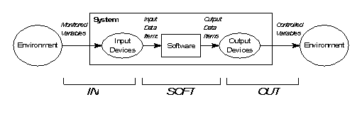
The SPARK software being designed using INFORMED typically forms part of a larger system which is likely to have interactions with the physical outside world. The first step is to delineate this boundary and identify the physical inputs and outputs. These are the environmental quantities that influence, or are influenced by, the system’s behaviour. They are described as monitored and controlled variables in the Four-Variable Model of Parnas and Madey [2], which describes the interactions between a computer system and the environment as follows:
A possible effect of this initial step might be the discovery that there is not a single system but a number of co-operating systems that can be designed separately.
5.2 Identification of the SPARK Boundary
It is unlikely that the entire system delineated in the previous steps will be implemented entirely in SPARK. For example some physical inputs might be processed in hardware before being used as software inputs, calls to board-level utility routines might be made or Ada subprograms implemented in assembly language. Even if the system could be entirely SPARK the design objective of having annotations in application domain terms may make it undesirable to do so. For example a sensor might be read via an Ada variable attached to a memory-mapped port with an address clause; however, we might still prefer to annotate our use of this sensor in terms such as “boiler temperature” rather than the physical identity of the variable from which it is obtained. This is even more the case when logically separate signals are read from a single variable. For example, “busy”, “paper out” and “error” signals for a printer might be read as separate bits of a single word interface: we certainly might want to treat these signals as different in application-level annotations rather than regard them as all coming from variable “printer-port”. The need to separate such signals will be even stronger where inputs and outputs occur through different bits of a single register or memory-mapped variable.
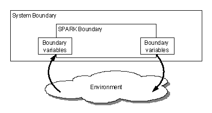
Selection of the boundary variables effectively defines the SPARK system boundary. The abstracted input/output values provided by the boundary variables (and boundary variable abstraction layers) are the Input Data Items and Output Data Items of the Parnas model [2]. Processing between the SPARK boundary and the System Boundary (and in abstraction layers) provides the processing described in the IN and OUT relations of Parnas.
The analysis may show that there is benefit from having more than one SPARK system within the overall system boundary. This is most likely when there is a significant amount of input/output processing required. Although this could be implemented in SPARK there are advantages in changing the scale or level of detail at which the data is considered in different parts of the system. One SPARK process can have relatively detailed boundary variables and produce a set of outputs which are read in more abstract form by a boundary variable of a second SPARK process. Often this can all be done within a single SPARK boundary by using boundary variable abstraction layers and normal SPARK refinement; however, there are cases where a division into two subsystems with manual analysis of the join is necessary.
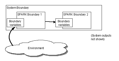
Here the first SPARK sub-system might be concerned with monitoring data received over data bus; this data might include, say, temperature and pressure. The boundary variables of this system would be concerned with terminal sub-addresses and other facets of bus communications. The sub-system could readily be implemented in SPARK and analysed to show that received messages were derived from the data bus as expected.
The second SPARK sub-system might implement a control algorithm that depended on temperatures and pressures obtained from the data bus. While it would be possible to join the two sub-systems together directly as a single SPARK program this would involve annotating the control sub-system in terms of the data bus despite the fact that at this point we wish to think in terms of domain entities such as temperature and pressure levels. The solution is to provide the second sub-system with a set of boundary variables at the level of abstraction appropriate to that sub-system (in this case streams of temperatures and pressures). In the body of these boundary variables the values will be obtained from the data bus by calls to routines exported by the first sub-system. Manual analysis of the join is necessary to show that a “GetTemperature” call in a boundary variable of the second sub-system maps correctly on to calls in the first sub-system that result in the current temperature being returned.
The extra effort is rewarded by:
· increased encapsulation of the interface details because the existence of the data bus is no longer visible at the control algorithm level;
· simplified reasoning about the behaviour of the control algorithm because the information we are processing is presented at an appropriate level of abstraction; and
· more meaningful annotations of the control algorithm with, for example
--# derives Heater.State from Temperature.State &
ReliefValve.State from Pressure.State & ...
replacing
--# derives Heater.State,
ReliefValve.State from Bus.State & ...
The cycle computer case study at Section 10 illustrates a system implemented as two co-operating SPARK sub-systems.
5.3 Identification and Localization of System State
Most realistic, useful systems store data values in variables and therefore have “history” or “state”. Selecting appropriate locations for this state is probably the single most important design decision that influences the amount of information flow in the system. The decisions involve deciding what must be stored, where must it be stored and how should it be stored. The significance of these decisions cannot be overestimated: it is the presence of system state that causes most of the complexity in understanding, analysing and testing code. In the absence of state, invoking an operation with a particular set of arguments always returns a consistent answer; in the presence of state the answer may also depend on some complex history of all previous calls.
5.3.1 What must be stored?
Some static data storage is likely to be unavoidable but the amount should be reduced as far as possible. An important principle is to avoid data duplication: data should be stored where it can be made be available to its users by means of suitable “accessor functions” rather than by sending copies to be stored by potential users. This guidance does not prohibit the passing of data as actual parameters to an operation; it is the static storage of copies of data that should be avoided.
A clear distinction should be made between state essential to the core functionality of the application and that added in for peripheral reasons such as to allow monitoring during dynamic testing.
5.3.2 Where should it be stored?
Data stored inside the main program does not appear in its annotations; this principle could be abused because, if all boundary variables and other state were embedded in the main program, it would have the uninformative dependency relation “--# derives ;”. As a first guideline, abstract own variables representing the external environment and state variables that we want to show the main program influencing should be outside it. Other, incidental, state should be inside the main program.
Although some representation of static data external to the main program must appear in its annotations, the use of SPARK refinement to give a hierarchical structure to that data gives control over the level of detail that must be described.
5.3.3 How should it be stored?
We can store static data in a number of ways:
· in a variable package at library level (global state);
· in a variable package embedded in (or a private child of) another variable package (hierarchical state refinement);
· in a variable package embedded in the main program;
· as an instance of a type package; or
· as a concrete Ada variable.
As a general rule, static state should be localised as much as possible and should be avoided entirely where a local variable within a subprogram will suffice. Type packages are especially beneficial because they give extra freedom to locate items of perhaps quite complex state as locally as possible. Variables declared within the main program retain their values for the life of the program whereas those declared in other subprograms exist only for the life of that subprogram.
Much OOD literature gives rather simplistic advice about the choices presented here. The usual advice is to represent a single instance of a data item as a variable package and to use a type package definition where multiple copies may be required. To these simple options we need to add consideration of whether the data needs to be shared, where it must be located if it is to be shared and what effect will that location have on the information flow of the system. Other considerations are the intended life of the data: must it exist continuously for the entire life of the program or is it only used intermittently?
The small compiler case study at Section 9 illustrates the way these choices can be made.
5.4 Handling Initialization of State
Having decided on the location and method of representing the persistent state of a system (i.e. state declared in packages as revealed by SPARK’s own variable annotation), early consideration needs to be given to how it will be initialized. SPARK makes particular demands in this area which can have a significant effect on program designs. The SPARK rules are required in order to be able to check that there are no overall data flow errors at the main program level.
5.4.1 Kinds of Initialization
State variables can be initialized using two distinct and separate approaches, each of which can be implemented in several ways.
|
Initialization Kind |
Initialization Method |
|
Initialization during program elaboration; the variable is considered to have a valid value prior to execution of the main program. |
· By execution of statements in a package’s elaboration part (i.e. between the begin and end of the package’s body). · By providing an initial value at the point of the variable’s declaration: X : Integer := 0; Note that SPARK imposes limits on what may appear in the initialization expression. · Implicit initialization by the external environment. Typically this is the case with boundary variables representing external data streams (see Section 3.5 and Appendix A). Other, less satisfactory, cases can occur where systems rely on RAM clearance to initialize state variables. |
|
Initialization during execution of the main program by a program statement. The variable does not have a valid value prior to execution of the statement concerned. |
· By an assignment statement. For concrete Ada variables any suitable expression may be assigned; for variables of type packages a suitable deferred constant or function call will be required. · By a call to a procedure which exports (and does not import) the variable concerned; this is the only way of initializing a variable of a type package implemented as an Ada limited private type. |
Table 1: Kinds of Intialization
5.4.2 Initialized Own Variables
Own variables initialized during elaboration are known as initialized own variables and are annotated with the SPARK --# initializes annotation, those initialized during program execution are not. The difference between initialization during elaboration and initialization after execution of the main program starts is fundamental and can be seen in the annotations of the main program.
External own variables (i.e. those declared with a mode) are also regarded as being initialized prior to the execution of the main program. In this case the initialization is provided implicitly by the environment.
Initialized own variables and external variables of mode IN may, and usually will, appear as imports in the main program’s derives annotation.
Other own variables may not appear as imports in the main program’s derives annotation.
The desired content of the main program’s annotations will thus influence how we choose to initialize state variables. Consider a tiny SPARK program that transfers data from boundary variable “Input” to boundary variable “Output” via a global variable package “Queue”. If we choose to initialize Queue.State at elaboration the derives annotation of the main program would be:
--# derives Output.State,
--# Queue.State
--# from Queue.State,
--# Input.State;
which correctly shows a dependency on the initial state of the Queue. However, if we choose to initialize the Queue by a subprogram call from within the main program the annotations become:
--# derives Output.State,
--# Queue.State
--# from Input.State;
from which it is much clearer that the Output depends only on the Input. The annotation also shows separately the side effect of the process on the Queue.
We can of course make the annotations in this example clearer still if we recognise that the Queue does not need to be a global variable and hence could be made to disappear entirely from the main program annotation; this leaves:
--# derives Output.State,
--# from Input.State;
5.5 Handling Secondary Requirements
As mentioned in Section 4.3, software designers frequently have to reconcile conflicting requirements. Amongst these requirements are some which INFORMED describes as “secondary requirements” because, although they may be important to the success of the project, they are not derived from the core functionality of the system being designed. The term “secondary” does not imply that these requirements are unimportant but rather that they should be accommodated in ways which do not distort the purity of the system design; they should not be allowed to dominate the design process to the extent that the design clearly deviates from the ideal. The issues at stake here are much more than just aesthetic; poor designs will be hard to test, develop and maintain — if the poor design results from thoughtless handling of an essentially secondary issue then a very unsatisfactory trade-off has been achieved.
An example may help clarify what we mean by secondary design issues. A program needs to make use of a buffer in the form of an array. The buffer needs to be greater than 64Kbytes in size for the program to function correctly but the processor/compiler combination has a limitation that prevents static arrays of greater than 64Kbytes being declared; however, there is a workaround in that a larger array can be declared on the system heap and accessed via a pointer. The requirement that the buffer be located on the heap is clearly a secondary requirement: from the pure, functional point of view of the application we care only that there is a buffer, we probably don’t care that it is an array and certainly don’t care where it is located. This does not make the requirement unimportant however, because if we want a buffer greater than 64Kbytes using our hypothetical processor/compiler combination we have no choice but to put it on the heap. What we must do is reconcile the need to keep the design pure with this secondary requirement; this will not be achieved if we allow the fact that a pointer is being used to leak out into the rest of the design and appear across the entire system. A solution in this particular case might be to declare the buffer as a variable package or instance of a type package so that knowledge of its location on the heap is confined to a single package. The design remains pure because the application deals only with the abstract buffer and the secondary requirement has been met because the buffer is placed on the heap. When a sensible compiler without the restriction replaces the current one, only one package will need to be altered if we choose to remove the array from the heap and declare it statically.
Some common situations that can result in design distortions are considered in Appendix B and possible palliatives suggested.
5.6 Implementing the internal behaviour of components
Application of the INFORMED steps identifies components such as variable packages, boundary variables and type packages and their relationships. Initially only annotated specifications for these objects are required allowing early static analysis of the design. Eventually the stage is reached when the consideration must be given to implementing the desired behaviour of each object.
The first step should always be to see whether decomposition into further, smaller INFORMED components is possible. For example a type package which exports a private type might be decomposed further by implementing the private type as a record with fields of a number of simpler private types each provided by a new type package which would be added to the design. This case is illustrated in the cycle computer case study at Section 10.4 where a type package identified to supply average speeds is decomposed into two smaller type packages providing respectively: an overall journey average speed; and a short term rolling average for smoothing purposes. Similar decompositions are frequently possible for variable packages and boundary variables.
When no further decomposition is beneficial the desired behaviour of the various objects is best achieved by a classic top-down refinement process. It is still possible and desirable to defer implementation of detail during this process and this is readily achieved by declaring and annotating local subprograms as place holders for operations required but not yet perhaps well enough understood to implement. If the bodies of such subprograms are hidden (or left as stubs for later completion with a subunit) then analysis using the Examiner can continue on the partial implementation throughout this phase. If for example we identify the need to sort a buffer we can defer implementation of the sort algorithm and continue both coding and flow analysis by providing the following procedure at the appropriate point:
procedure Sort(B : in out BufferType)
--# derives B from B;
is
--# hide Sort;
end Sort;
An extended example of this process, in the form of progressive top-down refinements of a lift controller, can be found in [1] chapter 14.
The above design steps are best demonstrated and illustrated by means of examples. Several case studies are presented, increasing in complexity, each intended to bring out specific ideas.
It is important to note that the INFORMED method does not depend on the use of any specific graphical notation since it is intended to produce textual descriptions of object oriented designs which can be analysed incrementally by the Examiner. Graphical notations may be of value during the earlier architectural design phase and there should be no difficulty expressing INFORMED designs using any of the common notations such as UML.
The following simple notational conventions are used to describe the case studies.
Arrows joining design elements show that the element at the arrow head is used (inherited) by the element at the arrow’s tail; solid arrows show close coupling through dependency on state and dashed arrows show weak coupling through use of a type or its services. SPARK annotations indicate the degree of coupling: the appearance of a package name as a prefix in a global or derives annotation indicates strong coupling; appearance only in an inherit annotation is weak coupling. Hierarchy is shown by grouping elements in boxes.
6.2 Overview of the Case Studies
The case studies are intended to illustrate various important aspects of the INFORMED approach. They are not necessarily complete or fully realistic. Certainly the requirements are rather vague and could be greatly improved by application of Praxis’ REVEAL approach to requirements capture.
Some of the case studies include substantial amounts of implementation at source code level; this is quite deliberate. It often seems that logical inconsistencies in design are only revealed when attempts are made to implement them using the rather formal notation of a programming language. It is also not uncommon for such inconsistencies to be “coded round” leading to loss of desirable properties such as loose coupling and to implementations that are hard to maintain and modify. Because INFORMED considers such issues from the start, the designs it produces should be easy to implement without the need to compromise their shape and structure.
The first case study, a boiler water contents control system is mainly concerned with sensors, actuators and system boundary issues. The use of a type package to provide two similar data structures is illustrated. Finally, the value of annotations in identifying inadequate cohesion of a subprogram is shown.
The heating control system in the second study adds boundary variable abstraction layers and shows how type packages facilitate configuring the system for different buildings by data, rather than executable code, changes only.
Both of these examples are provided with almost complete implementations in SPARK.
The third example, an outline of a tiny compiler, is mainly concerned with the consequences arising from choices in the location of system state variables. It draws the, perhaps surprising, conclusion that type packages have some important advantages over variable packages even when only a single instance of each is required by the design. This study also illustrates a use for utility packages.
The final example, a cycle computer, introduces implementation of a design using co-operating SPARK subsystems, reinforces the concept of boundary variable abstraction and shows type packages can be used in hierarchies. The cycle computer also illustrates systems with differing “modes” of behaviour, in this case the normal operating mode and the less frequent mode for programming the unit with the bicycle’s wheel size.
In Section 11, after the case studies, some further general observations on information flow and coupling are made.
A device is needed to monitor the depth of water in a boiler vessel. Two sensors are provided “water low” and “water high”. When the water is low a fill valve is to be opened. When the water is high a drain valve is to be opened. When neither high nor low signal is present both valves are closed. To prevent the valves chattering some delay of operation is required with the valves only operating after 10 successive, consistent signals have been received from the associated sensor.
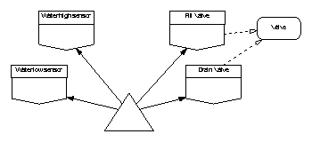
The system boundary encompasses the water vessel itself, the valves and the sensors. Presumably other things are going on such as heating the water and taking off steam; however these are outside the system boundary. The physical inputs are “water high” and “water low” signals although at this stage the manner in which they are provided is not specified. The physical outputs are the “fill valve” and “drain valve” which we can operate in some, as yet unspecified way.
To establish the SPARK boundary we consider the problem domain entities that we wish to appear in the main program’s annotations. We could take a slightly abstract view and say we were concerned only with “sensors” and “actuators” but this would leave us unable to reason about whether the fill valve opened in response to a low or high water level. For such a simple system we can take the physical inputs and outputs identified above directly. We therefore identify four boundary variables: “water high sensor”, “water low sensor”, “fill valve” and “drain valve”. Outside the SPARK boundary will be the implementations of those boundary variables and the precise way that the logical signal “water high” is obtained from the physical environment.
The value of signals “water high” and “water low” can be considered Boolean; however, valves are normally Open or Shut. Since we have two specific valves (Fill and Drain) that share this characteristic this suggests the need for a type package to represent this shared characteristic of valves.
There does not appear to be any value in boundary abstraction layers since high and low sensors are logically separate and are not natural candidates for combining in this way. The system thus far comprises the four boundary variables, a type package and, an as yet unspecified main program.
Next we identify the essential state of the system. We need to store counts of the number of times the sensors have recorded the water being high or low so as to implement the requirement to only act when 10 successive hits have been recorded. Where should this state be located? There are several options.
7.2.1 In global variable packages used by the main program
Here we would add two “fault accumulator” variable packages to the system. The main program would poll the raw sensor values and, if an event was registered, update the appropriate variable package. A function exported by the variable package would indicate when sufficient events had been recorded for an actuator to be used. Clearly the state of the variable packages would be external to the main program and thus appear in its global and derives annotation; however, the function of the main program is to provide a functional link between the sensors and actuators not to push information into and read it from the fault accumulators. This solution clearly causes unnecessary information flow and is inappropriate. A further objection is that 2 identical variable packages would be needed, one for each sensor.
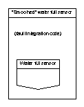
7.2.2 Inside the sensor boundary variables
This would have the effect of making the counting of occurrences part of the IN relation of the Parnas model. This is a better solution because the information flow of the main program would be solely in terms of “smoothed” sensor stream values and actuator stream values. No unnecessary information flow would be taking place. Set against this would be the enlargement of both sensor boundary variables with identical fault integration code. Such duplicated code might also be outside the SPARK boundary (because it would be in the body of the boundary variable packages which might perhaps not be implemented in SPARK) and would not therefore be subject to static analysis despite being capable of being expressed in SPARK.
The latter objection could be covered by performing the fault integration of each sensor in a variable package which encloses the boundary variable (use of hierarchy) either by embedding as shown below or by making the boundary variable a private child; however, this would still need code duplication. Nonetheless, the use of abstraction layers to provide smoothed, calibrated or otherwise processed input data is a useful technique which is illustrated further in the heating control system case study at Section 8.
7.2.3 As local variables inside the main program
Entities placed inside the main program do not appear in its annotations. Since we want the main program’s annotations to be in terms of the sensors and actuators only, this makes performing fault integration within the main program a possible solution. We may want to reason that the requirement for delay in operating the actuators is implemented correctly thus giving an advantage to making the fault counting visible within the main program rather than hiding it in the boundary variables.
If we provisionally decide to make the count history into local variables of the main program how should they be represented? We could use discrete Ada local variables and increment them and decrement them explicitly in response to the values obtained from the sensors; however, this will clearly involve code duplication and force an early commitment to concrete representation forms. We could use variable packages as fault integrators but, in contrast to the first rejected option, embed these inside the main controller. This would achieve abstraction (which concrete Ada variables would not) and keep fault integration issues out of the main program annotations. The remaining drawback would be code duplication: two identical embedded variable packages would be needed.
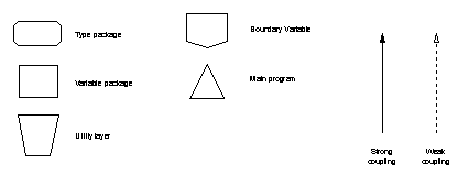
The best option therefore seems to be to declare two variables, local to the main program, which are instances of a type package; this locates the state in the correct place and allows sharing of the fault integration code. The proposed architecture is a loop-free partial ordering thus:
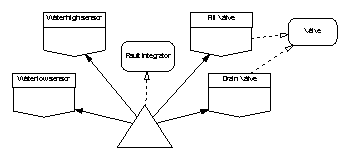
Finally we consider initialization. The sensors can be considered initialized by the environment because the water will be at some level, outside the software control, when the sensors are first inspected. The associated own variables of these boundary variables will therefore include modes making them external variables. The valves could be initialized by their boundary variables at system elaboration (presumably by setting them closed); however, it will probably simplify reasoning about correct start up (as well as improve the main program annotations) if we choose explicitly to shut the valves at the start of the main program. The fault integrators will also require initialization. Since SPARK does not permit default values for types (including type packages) some explicit initialization routine (or deferred constant) will need to be exported by the type package. We can use this routine to set the hysteresis threshold for each instance of the type package thus avoiding problems if the required count of the low and high water sensors became different due to a requirement change. Our state location choices do not need to change for initialization considerations.
We now have a complete design framework allowing an analysable main program to be written. We can produce a text version of the design using the templates introduced earlier and by writing a (partial) package specification for the fault integrator type package.
package WaterHighSensor
--# own in State;
is
function IsActive return Boolean;
--# global in State;
end WaterHighSensor;
---------------------------------------------------
package WaterLowSensor
--# own in State;
is
function IsActive return Boolean;
--# global in State;
end WaterLowSensor;
---------------------------------------------------
package Valve
is
type T is (Open, Shut);
end Valve;
---------------------------------------------------
with Valve;
--# inherit Valve;
package FillValve
--# own out State;
is
procedure SetTo(Setting : in Valve.T);
--# global out State;
--# derives State from Setting;
end FillValve;
---------------------------------------------------
with Valve;
--# inherit Valve;
package DrainValve
--# own out State;
is
procedure SetTo(Setting : in Valve.T);
--# global out State;
--# derives State from Setting;
end DrainValve;
---------------------------------------------------
package FaultIntegrator
is
type T is limited private;
procedure Init(FI : out T;
Threshold : in Positive);
--# derives FI from Threshold;
procedure Test(FI : in out T;
CurrentEvent : in Boolean;
IntegratedEvent : out Boolean);
--# derives IntegratedEvent,
--# FI from FI, CurrentEvent;
private
--# hide FaultIntegrator;
end FaultIntegrator;
---------------------------------------------------
with WaterHighSensor,
WaterLowSensor,
Valve,
FillValve,
DrainValve,
FaultIntegrator;
--# inherit WaterHighSensor,
--# WaterLowSensor,
--# Valve,
--# FillValve,
--# DrainValve,
--# FaultIntegrator;
--# main_program;
procedure Main
--# global in WaterHighSensor.State,
--# WaterLowSensor.State;
--# out FillValve.State,
--# DrainValve.State;
--# derives FillValve.State
--# from WaterLowSensor.State &
--# DrainValve.State
--# from WaterHighSensor.State;
is
HighIntegrator,
LowIntegrator : FaultIntegrator.T;
HighThreshold : constant Positive := 10;
LowThreshold : constant Positive := 10;
procedure Control
--# global in WaterHighSensor.State,
--# WaterLowSensor.State;
--# out FillValve.State,
--# DrainValve.State;
--# in out HighIntegrator,
--# LowIntegrator;
--# derives FillValve.State,
--# LowIntegrator
--# from LowIntegrator,
--# WaterLowSensor.State &
--# DrainValve.State,
--# HighIntegrator
--# from HighIntegrator,
--# WaterHighSensor.State;
is
--# hide Control;
end Control;
begin -- Main
FaultIntegrator.Init(HighIntegrator, HighThreshold);
FaultIntegrator.Init(LowIntegrator, LowThreshold);
FillValve.SetTo(Valve.Shut);
DrainValve.SetTo(Valve.Shut);
loop
Control;
end loop;
end Main;
This is a complete framework for the water contents control program; furthermore, it can be analysed by the Examiner to ensure that there are no unexpected dependencies in the information flow. The code cannot yet be compiled because the body of package FaultIntegrator is missing, the private part of FaultIntegrator is hidden and the body of procedure Control is also hidden.
The design process now shifts to one of top-down refinement. Firstly we consider procedure Control. Checking the derives annotation for the procedure clearly shows that it is performing two separate functions: there is a relation between the Fill Valve, the Water Low Sensor and the Low Integrator and a similar but separate relation between the Drain Valve, Water High Sensor and High Integrator. The control procedure is therefore doing two things, not one, which suggests that optimal cohesion is not being achieved. Although we clearly could code the procedure to match the annotation testing it or proving it correct would be complicated by its dual function. Since (ignoring sensor failures) it is a physical property of the system that the water level cannot simultaneously be too high and too low a likely consequence would be the introduction of non-executable paths. For example, a straightforward implementation of Control:
procedure Control
...
is
RawTooFull,
RawTooEmpty,
TooFull,
TooEmpty : Boolean;
begin
RawTooFull := WaterHighSensor.IsActive;
RawTooEmpty := WaterLowSensor.IsActive;
FaultIntegrator.Test(HighIntegrator,
RawTooFull,
--to get
TooFull);
FaultIntegrator.Test(LowIntegrator,
RawTooEmpty,
--to get
TooEmpty);
if TooFull then
DrainValve.SetTo(Valve.Open);
else
DrainValve.SetTo(Valve.Shut);
end if;
if TooEmpty then
FillValve.SetTo(Valve.Open);
else
FillValve.SetTo(Valve.Shut);
end if;
end Control;
would produce four apparent execution paths, one of which is non-executable (and therefore non-testable) due to environmental or physical constraints.
The dual function of Control suggests that either it should be split or implemented as two smaller, embedded procedures. Since Control is called only from the main loop it is simpler to split it into one procedure to monitor high water levels and one to monitor low:
procedure ControlHigh
--# global in WaterHighSensor.State;
--# out DrainValve.State;
--# in out HighIntegrator;
--# derives DrainValve.State,
--# HighIntegrator
--# from HighIntegrator,
--# WaterHighSensor.State;
is
RawTooFull,
TooFull : Boolean;
begin
RawTooFull := WaterHighSensor.IsActive;
FaultIntegrator.Test(HighIntegrator,
RawTooFull,
--to get
TooFull);
if TooFull then
DrainValve.SetTo(Valve.Open);
else
DrainValve.SetTo(Valve.Shut);
end if;
end ControlHigh;
and
procedure ControlLow
--# global in WaterLowSensor.State;
--# out FillValve.State;
--# in out LowIntegrator;
--# derives FillValve.State,
--# LowIntegrator
--# from LowIntegrator,
--# WaterLowSensor.State;
is
RawTooEmpty,
TooEmpty : Boolean;
begin
RawTooEmpty := WaterLowSensor.IsActive;
FaultIntegrator.Test(LowIntegrator,
RawTooEmpty,
--to get
TooEmpty);
if TooEmpty then
FillValve.SetTo(Valve.Open);
else
FillValve.SetTo(Valve.Shut);
end if;
end ControlLow;
A corresponding change to the main control loop is needed introducing separate control procedures for the two modes of the system (controlling the too empty state and controlling the too full state) as suggested in Section 3.1:
...
loop
ControlHigh;
ControlLow;
end loop;
...
Finally, we need to supply the missing details of the fault integrator using top-down refinement. The requirements for the fault integrator are rather vague and would need clarification; however, the implementation shown here is fairly typical and serves to prevent the valves chattering open and closed when the water is close to a threshold value. The abstract fault integrator type can be implemented as a record recording the threshold at which action is required, the current number of raw events seen and whether the output is currently tripped:
private
type T is record
Limit : Positive;
Counter : Natural;
Tripped : Boolean;
end record;
end FaultIntegrator;
The package body is straightforward:
package body FaultIntegrator
is
procedure Init(FI : out T;
Threshold : in Positive)
is
begin
FI := T'(Limit => Threshold,
Counter => 0,
Tripped => False);
end Init;
procedure Test(FI : in out T;
CurrentEvent : in Boolean;
IntegratedEvent : out Boolean)
is
begin
if CurrentEvent then
if FI.Counter = FI.Limit then
FI.Tripped := True;
else
FI.Counter := FI.Counter + 1;
end if;
else -- no CurrentEvent
if FI.Counter = 0 then
FI.Tripped := False;
else
FI.Counter := FI.Counter - 1;
end if;
end if;
IntegratedEvent := FI.Tripped;
end Test;
end FaultIntegrator;
This is the final ingredient of a complete implementation of the design.
This example is based on a case study in [3]. A building has a number of rooms each containing one or more temperature sensors and one or more heaters. A central controller is required to switch the heaters on in each room that is below the desired temperature and off in rooms at or above the desired temperature. Where more than one sensor is provided in a room, the controller uses a mean of their readings.
The system boundary encompasses the rooms, temperature sensors and heater actuators. People lighting log fires in some rooms and opening windows in others are outside the system boundary. The physical inputs are the temperature of each individual sensor. The physical outputs are the actuator switches for each individual heater.
As with the water-level controller we consider the problem domain entities that we wish to appear in the main program’s annotations. We could have a boundary variable for each sensor and switch; however, where there was not a one-to-one relationship between rooms, sensors and heaters the main program annotations would become rather messy. Furthermore, the annotations would have to change if the building configuration changed in any way. We need to be able to ask for the abstracted temperature (which may be the mean of several sensors) of any room and set a logical heat signal (which may turn on more than one heater) for any room. This suggests a boundary variable for “room temperatures” and one for “room heaters”. Since both need to select the room they are dealing with they clearly share a “room” object which appears to be a type package. Our initial design takes the form:
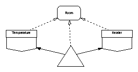
The very simple control required by this system means that it does not have to retain any “state” variables; each room is checked in turn and its associated heater turned on or off as appropriate. We might choose to use “fault integration” as in the previous example but this has been omitted in this case for simplicity. We can already represent this design using INFORMED design element templates and flow analyse it. Note, however, that we have ignored for now the relationship between our chosen boundary variables and their physical interfaces and the fact that this is not a one-to-one relationship; this suggests that our boundary variables may actually turn out to be boundary abstraction layers, with some internal state, as the design is refined; because of this we choose not to make the own variables external in this case. Our first textual representation is thus:
package Room
is
type T is (One, TheRest); -- deferred decision on number of rooms
end Room;
-------------------------------------------------------
with Room;
--# inherit Room;
package Temperature
--# own State; -- represents both sensors and whatever internal state proves to be needed
--# initializes State;
is
type T is range -30 .. 60; -- Celsius
procedure Poll;
--# global in out State;
--# derives State from State;
function Reading(TheRoom : Room.T) return T;
--# global State;
end Temperature;
-------------------------------------------------------
with Room;
--# inherit Room;
package Heater
--# own State;
--# initializes State;
is
type T is (On, Off);
procedure SetSwitch(TheRoom : in Room.T;
Setting : in T);
--# global in out State;
--# derives State
--# from State,
--# TheRoom,
--# Setting;
end Heater;
-------------------------------------------------------
with Room,
Temperature,
Heater;
use type Temperature.T;
--# inherit Room,
--# Temperature,
--# Heater;
--# main_program;
procedure Main
--# global in out Temperature.State,
--# Heater.State;
--# derives Heater.State,
--# Temperature.State
--# from *,
--# Temperature.State;
is
procedure Control
--# global in out Temperature.State,
--# Heater.State;
--# derives Heater.State,
--# Temperature.State
--# from *, Temperature.State;
is
Desired : constant Temperature.T := 18;
begin -- Control
Temperature.Poll;
for TheRoom in Room.T
loop
if Temperature.Reading(TheRoom) < Desired
then
Heater.SetSwitch(TheRoom, Heater.On);
else
Heater.SetSwitch(TheRoom, Heater.Off);
end if;
end loop;
end Control;
begin -- Main
loop
Control;
end loop;
end Main;
Although this is a complete and analysable outline design for the heating control system it ignores important details that need to be addressed in a complete implementation. In particular, it ignores the mapping of physical sensors and heaters to the rooms in which they are situated.
We could decide that all this detail resided in the body of packages Temperature and Heater and therefore lay outside the SPARK boundary; however, this would unnecessarily restrict the portion of code which could be written in SPARK and analysed. Instead we decide to treat packages Temperature and Heater as boundary abstraction layers and refine them in terms of embedded (or private child) boundary variables. In the interests of flexibility we would clearly prefer the mapping of physical sensors/heaters to rooms not to be achieved by hard-coded control flow but rather by being treated as data.
Taking the temperature sensors first we can conduct a mini INFORMED design process to obtain the required behaviour of the Temperature boundary abstraction layer. The package provides an abstraction for physical temperature sensors so we need a boundary variable to represent these. We could have one boundary variable for each sensor but since their characteristics are all the same it is simpler to have a single boundary variable for all the physical sensors with the individual sensor value required being controlled by a parameter. The mapping of physical sensors to rooms is constant for any particular instantiation of the controller and is therefore not considered “state” by SPARK; a constant look up table should suffice to describe it. Finally we need a way of constructing mean temperatures for each room as a result of reading the physical sensors that map to that room. It would be convenient to be able to allocate each physical reading as it is taken to the room to which it belongs and then, separately, to be able to obtain the mean temperature reading for each room; this suggests some form of “temperature accumulator” object which will store this state. Since we need one such object for each room a type package is the appropriate implementation. The design for the Temperature boundary abstraction layer is thus:
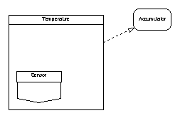
The accumulator type package is straightforward to specify; however, since it accumulates temperatures it needs to share the definition of the temperature types with package Temperature. This definition must be moved to a type package.
package Celsius
is
type T is range -30 .. 60;
end Celsius;
-------------------------------------------------------
with Celsius;
--# inherit Celsius;
package Accumulator
is
type T is private;
Clear : constant T;
procedure Add(TheAccumulator : in out T;
Value : in Celsius.T);
--# derives TheAccumulator from *, Value;
function Mean(TheAccumulator : T) return
Celsius.T;
private
--# hide Accumulator;
end Accumulator;
Implementing the body of Temperature makes use of SPARK’s refinement mechanism. We have already described Temperature as having state and indicated this with an own variable annotation; however, in the earlier version this state represented just an external environmental input, now it represents both this and some actual state stored in the boundary abstraction layer. The embedded boundary variable Sensor will have an external own variable to represent its interaction with the physical world. We have also identified the need to accumulate raw temperature values in order to construct mean temperatures for each room; this too is an element of state. The state of Sensor and the stored temperatures are refinement constituents of the abstract state of Temperature.
with Accumulator;
package body Temperature
--# own State is in Sensor.State, AccumulatedValue; -- refinement clause
-- the Sensor.State component is an external variable
is
PhysicalSensorCount : constant := 10;
type SensorNumber is range 1..PhysicalSensorCount;
-- define look up table for physical sensors to rooms
type SensorMapping is array(SensorNumber) of Room.T;
SensorToRoom : constant SensorMapping :=
SensorMapping'(SensorNumber => Room.TheRest); -- mapping details
-- deferred
-- create store for accumulated values for each room (must be initialized because
-- abstract state is initialized)
type AccumulatedValues is array(Room.T) of Accumulator.T;
AccumulatedValue : AccumulatedValues :=
AccumulatedValues'(Room.T => Accumulator.Clear);
-- embedded boundary variable to read physical sensors – could also be private child
--# inherit Temperature, Celsius;
package Sensor
--# own in State;
is
function Read (TheSensor : Temperature.SensorNumber)
return Celsius.T;
--# global State;
end Sensor;
package body Sensor is separate; -- and outside SPARK boundary
procedure Poll
--# global in Sensor.State;
--# out AccumulatedValue;
--# derives AccumulatedValue from Sensor.State;
is
LocalAccu : Accumulator.T;
AssociatedRoom : Room.T;
SensorReading : Celsius.T;
begin
AccumulatedValue := AccumulatedValues'(
Room.T => Accumulator.Clear);
for CurrentSensor in SensorNumber
loop
AssociatedRoom := SensorToRoom(CurrentSensor);
-- local variable needed to conform to entire variable rule (see [1] page 131) in call to Add
LocalAccu := AccumulatedValue (AssociatedRoom);
SensorReading := Sensor.Read (CurrentSensor);
Accumulator.Add (LocalAccu, SensorReading);
AccumulatedValue (AssociatedRoom) := LocalAccu;
end loop;
end Poll;
function Reading(TheRoom : Room.T) return Celsius.T
--# global AccumulatedValue;
is
begin
return Accumulator.Mean(AccumulatedValue(TheRoom));
end Reading;
end Temperature;
A similar approach could be taken to refining the Heater boundary abstraction layer with a look up table determining which physical heaters need to be switched on when heat for a particular room is demanded.
The final ingredient of the basic design is the implementation of the type package Accumulator. First we define a physical implementation of the, previously hidden, private type and deferred constant.
private
type AccumulatedTemp is range –300 .. 600;
-- allows for up to 10 sensors per room. Code would be more robust if the type bounds
-- were calculated in some way from a constant representing the maximum number of
-- sensors a room could have.
type T is record
Count : Natural;
Total : AccumulatedTemp;
end record;
Clear : constant T := T'(0, 0);
end Accumulator;
The type package can then be implemented.
with Celsius; -- second with clause needed to allow the use type which follows
use type Celsius.T;
package body Accumulator
is
procedure Add(TheAccumulator : in out T;
Value : in Celsius.T)
is
begin
TheAccumulator.Count := TheAccumulator.Count + 1;
TheAccumulator.Total := TheAccumulator.Total +
AccumulatedTemp(Value);
end Add;
function Mean(TheAccumulator : T) return Celsius.T
is
begin
return Celsius.T(TheAccumulator.Total /
AccumulatedTemp(TheAccumulator.Count));
-- to avoid a divide by zero we need to ensure that Add is always called at least once
-- before Mean; otherwise we need some defensive programming here
end Mean;
end Accumulator;
We now have a complete, analysable design for a generic implementation of the system. Instantiating the controller for a particular building requires only the setting up of the appropriate types and constants. Consider the following configuration:
|
Room |
Number of sensors |
Sensor number allocated |
|
One |
1 |
1 |
|
Two |
2 |
2, 3 |
|
Three |
1 |
4 |
|
Four |
3 |
5, 6, 7 |
|
Five |
1 |
8 |
Table 2: Heating example configuration data
This would require the following declarations to be modified:
package Room
is
type T is (One, Two, Three, Four, Five);
end Room;
...
PhysicalSensorCount : constant := 8;
...
SensorToRoom : constant SensorMapping :=
SensorMapping'(1 => Room.One,
2 | 3 => Room.Two,
4 => Room.Three,
5 | 6 | 7 => Room.Four,
8 => Room.Five);
The architecture of the finished design can be represented thus:
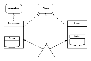
A useful design exercise would be to change the requirements so that configuring the controller for a different building did not require recompilation but only the setting of some data values in, perhaps, EPROM storage. The important design principle here would be that the configuration data might need to be implemented as variables but from the viewpoint of the controlling software is logically constant and therefore not “state”. Dealing with these issues was covered at Section 5.5 and Appendix B.
This example, which is left in outline form, is primarily intended to illustrate the consequences of design choices concerning where and how system state, or static data values, are located. A compiler is used as a vehicle for these illustrations but the case study is not intended to be a real compiler design and no implementation details are provided.
The compiler reads source files, writes object files and displays diagnostic messages; although all these files will be read and written using some standard file handling package we prefer to have the main program annotations showing object files being derived from source files rather than just deriving the state of the file system from itself. These considerations suggest the need for three boundary objects one for source files in, one for object file out and one for messages; this SPARK boundary selection gives the following outline design of the compiler.
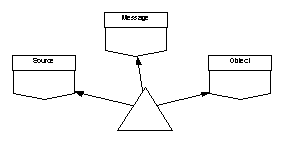
Assuming we cannot perform a line-by-line translation of source code to object code, the essential state of the system will consist of some intermediate representation of the source file in a form suitable for conversion to object code. For the purposes of this illustration we assume that this intermediate representation can be captured in three state items: a syntax tree; a symbol table capturing information such as variable types; and a string table providing efficient tokenized storage for the names given to identifiers.
There are some clearly identified processes taking place within the compiler that combine these data items in particular ways; this suggests that we might want to include some utility layers in the design. For example, there is a parsing process concerned with populating the syntax tree and string table from the source file; a wellformation checking process which populates the symbol table and may produce diagnostic messages; and a code generation process which writes object code files based on the syntax tree and symbol table. There is no overriding reason why these processes should not simply be local subprograms of the main program but since they are likely to be fairly complex items in their own right separating them into utility packages seems useful.
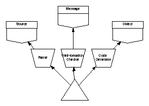
We can now consider the effect of making various choices for location of the three state items using the considerations outlined in Section 5.3.
Here we use a variable package for each of the syntax tree, symbol table and string table. The design would take the following form.
The state of packages SyntaxTree, Strings and Symbols is external to the main program and will therefore appear in its annotations. Since these variable packages are represented as library-level packages the state will appear in both the global and derives annotations of the main program. The global annotation will therefore be of the form:
--# global in Source.State;
--# out Message.State,
--# Object.State;
--# out SyntaxTree.State,
--# Strings.State,
--# Symbols.State;
We expect the compiler to derive both object code and diagnostic messages from the source code and this can be represented by the (partial) derives annotation:
--# derives Object.State,
--# Message.State from Source.State;
We can tell that this annotation is incomplete because it does not mention all the items in the list of global variables. Additional information flows concerning SyntaxTree.State, Strings.State and Symbols.State are also taking place. These are slightly inconvenient to reason about because they are not part of the core function of the compiler, being simply side effects of its production of the desired object code. The full derives annotation for the compiler main program is:
--# derives Object.State,
--# Message.State,
--# SyntaxTree.State,
--# Strings.State,
--# Symbols.State from Source.State;
Although this does capture the potentially important information that the states of the syntax tree and other packages is modified by the compilation process, and that their changed state depends only on the source file processed, we clearly have not achieved the minimum information flow we are seeking.
9.2 Hierarchical State Refinement
As mentioned in Section 5.3.2 we can use refinement to control the level of detail at which state must be described. From the previous design diagram it is clear that the state of syntax tree, string table and symbol table is very tightly bound; most operations use two of the three state components and the wellformation checker uses all three. One way of reducing the level of information flow that must be described in the main program annotation is therefore to use refinement to impose a hierarchy on the external state. We can do this by deciding that the states of the syntax tree, string table and symbol table are all components of some symbolic representation of the source file and that this symbolic representation can be represented by a single piece of state. This decision gives the following design:
As expected this does not remove the symbolic representation state from the main program annotations but does reduce the level of detail at which it must be described. The main program annotation becomes:
--# global in Source.State;
--# out Message.State,
--# Object.State;
--# out SymbolicRep.State;
--# derives Object.State,
--# Message.State,
--# Source.State,
--# SymbolicRep.State from Source.State;
which is only one line longer than the minimum achievable, rather than twice as long as in the unrefined case. Even though the use of refinement simplifies the main program annotation in this case, it is still clear that the annotation is describing information flow that perhaps should not be external to it at all.
Another potential disadvantage of this approach is that the reduction in size of the main program annotation has been bought at the price of a reduced level of detail at which all operations involving the syntax tree, string table and symbol table can be described. For example, the parser populates the syntax tree and string table from the source file but does not directly affect the symbol table. With the state abstracted into the single SymbolicRep.State, we can no longer make this distinction.
9.3 Variable Packages Embedded in the Main program
We could exploit the principle that entities local to the main program do not appear in its annotations and embed the syntax tree, string table and symbol table packages in the main program. Although this approach would reduce the main program annotation to the minimum size possible and leave it describing only external, boundary variable state, it has a number of rather serious disadvantages.
We could not exploit SPARK 95 child packages because it is not possible to have a child package of a subprogram; physical embedding of the packages would therefore be necessary. Since the syntax tree etc. are likely to be fairly large and complex this would make the main program very large.
More seriously, considerations of visibility, and the fact that variable packages cannot be passed as parameters, would mean that we could no longer employ our active utility layer packages Parser, WellformationChecker and CodeGenerator. The subprograms in these packages would have to be moved to the main program making it even larger.
Although embedding a package in the main program, to encapsulate some aspect of system state, is occasionally useful, it is clearly inappropriate in this case and this option is not considered further here.
9.4 Instances of a Type Package
Instead of representing the syntax tree, string table and symbol table in variable packages we can define a type package for each that captures its essential properties. The actual state for each can then be located in the main program by declaring an instance of each at that point. Although this approach results in the state being inside the main program it has fundamentally different properties than those associated with the embedding of variable packages described in the previous section. Crucially it becomes possible for the main program to pass the locally-declared variables as parameters to externally declared operations; this means that it is possible to retain the utility layers used to define the parser, wellformation checker and code generator. The resulting design is as follows:
Although the number of arrows on this diagram gives the impression that it is more coupled than its variable package equivalent, it is actually less coupled in information flow terms because each of the dashed arrows represents only weak (inherits) coupling which does not involve the flow of information. The extra inherit arrows from the main program are to allow the declaration of variables to represent the syntax tree, string table and symbol table within the main program; declared here they disappear from the main program’s annotations which are simplified to:
--# global in Source.State;
--# out Message.State,
--# Object.State;
--# derives Object.State,
--# Message.State from Source.State;
The locally-declared state variables are passed as parameters to the operations that need to manipulate them. For example, the syntax tree and string table will be out parameters of the “parse” operation declared in utility layer Parser. The annotations for these operations can still be described in full detail; for example, the parse operation has the annotation:
procedure Parse(SynTree : out SyntaxTree.T;
StringTab : out Strings.T);
--# global in Source.State;
--# derives SynTree,
--# StringTab from Source.State;
This clearly shows the parts of system state affected by parsing the source file and, in particular, that the operation does not affect the symbol table.
Notwithstanding the fact that there is only one syntax tree, one string table and one symbol table, the use of type packages to define them, and instances of those types to declare them in the main program, is clearly the best of the design options considered.
For the sake of completeness, we consider here the possibility of directly representing the system state in a number of concrete Ada variables declared in the main program. Although sharing some of the properties of the previous solution (in particular none of the state would appear in the main program’s annotations) the approach would greatly complicate the annotations of intermediate operations such as the parser. It is clear that rather than just deriving the abstract syntax tree this operation would now have to be described in terms of arrays, current node indexes and many other concrete, low-level variables. Any change to the implementation of the syntax tree would require a rework of the annotations of all operations that used it.
Premature use of concrete representations of data prevents proper encapsulation and abstraction and inevitably leads to closer coupling as indicated by growing SPARK annotations.
The final case study, again in outline form, is intended to include examples of all the techniques thus far introduced; for this reason the solution may not to be the simplest or best available.
The cycle computer consists of a display/control unit to mount on the handlebars of a bicycle and a sensor that detects each complete revolution of the front wheel. The display unit shows the current instantaneous speed on a primary display and has a secondary display showing one of: total distance, distance since last reset, average speed and time since last reset. The display/control unit has two buttons: the first resets the time, average speed and trip values; and the second switches between the various secondary display options. Unfortunately, but typically of many software projects, the hardware has already been designed.
There is a clock that provides a regular tick (but not time of day) and the sensor ¾ a reed relay operated by a magnet on the bicycle wheel ¾ provides a pulse each time the wheel completes a revolution.
10.2 Identification of System and SPARK Boundaries
The system inputs are the pulse stream from the wheel sensor, the clock tick and the two control buttons. The outputs are the primary and secondary displays. Of these only the wheel sensor pulses present any particular difficulty. If we wish to measure distance then we need only count the number of wheel pulses received; however, we also want to calculate speed and display that. For this purpose we need to know not just that a pulse has occurred but also the interval between pulses (or number of pulses in a given interval). A suitable abstracted input for the system would thus be a sequence of time stamps each indicating the time the most recent pulse occurred. Therefore, some part of the system will need to check the system clock each time a pulse occurs and store the time of that pulse. A practical method of doing that would be to make the wheel pulse signal generate an interrupt which runs a routine to interrogate the clock and store the time at which the pulse occurred. The rest of the system can be designed to read and process the sequence of time stamps thus generated. It is quite feasible to write the proposed interrupt routine as a SPARK main program; this suggests a possible solution comprising two co-operating SPARK sub-systems:
· handling the interrupt and generating the time-stamped pulse queue; and
· reading the time-stamped pulse queue and controls to provide the rest of the system functionality.
Each of these systems can be written in SPARK and analysed separately; they cannot be analysed together because a SPARK program cannot have two main programs. The two subsystems will share the clock and will communicate via a boundary object representing the time pulse queue. Our initial outline design thus takes the form:
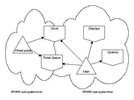
10.3 Boundary Variables and Boundary Abstraction Layers
The outline design above already identifies the principal boundary variables of the system. The pulse queue and clock are straightforward and require no further refinement. The controls and display, however, can be improved by addition of suitable boundary abstraction layers. The display has two, closely coupled, components: the primary (speed) and secondary (multi-purpose) displays. The controls comprise two buttons: reset and mode. Adding these abstraction layers to the larger of the two subsystems gives:
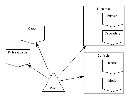
In SPARK 95, the boundary variables embedded in the boundary abstraction layers can conveniently be implemented as private child packages as illustrated at Section 3.5.1.
10.4 Identification and Location of Essential State
Some further information needs to be stored for the controller to perform its function.
· To calculate instantaneous speed we need (for smoothing purposes) a rolling average, over a short period, of values from the pulse queue.
· For average speed we need to calculate an average of values from the pulse queue but over the entire period since the reset button was last pressed.
· To display total distance travelled we need a count of the total number of pulses received since the system was first activated.
· For trip distance we need a count of the total number of pulses since the last reset.
· For the elapsed time or stopwatch function we need to record the clock tick value at the last reset.
· Finally, all calculated values depend on the wheel size which must be stored in a suitable location. For simplicity the routines that would be needed for the user to be able to program the wheel size into the device have been excluded at this stage.
We do not want the details of the calculation of rolling mean pulse values to appear in the main program’s annotations which suggests that they should be considered internal state of the main program. This could be achieved by declaring suitable discrete variables; however, the calculation of the mean values will involve, at least, counts of numbers of pulses and totals of intervals which would require several discretes or at least a record to hold them. This complexity suggests that the calculation of averages might best be achieved with the aid of an instance of a type package. Two separate averages need to be calculated (see above) but both will have the same input (timed wheel pulse); this suggests a hierarchy of type packages might be suitable. A single abstraction is used by the main program and takes the form of a record whose fields are of further type packages: one to handle the short-term rolling average and one to handle cumulative average speed for a journey.
The decision regarding total pulses received and total received since last reset is similar although the decision whether to use discrete variables or a type package is perhaps a closer call here. On the basis that more abstraction is usually better than less a type package is probably preferred. This type would handle both the trip and total pulse count using a single AddPulse call and provide an operation to reset the trip count and functions to return each of the trip and total pulse counts.
For the stop watch function we need to store a clock tick value which we can subtract from the current clock tick at any point to get an elapsed time. This is a simple integer-typed value best implemented as a concrete Ada variable local to the main program.
The final item, wheel size, offers more interesting design choices. Most straightforwardly, it could be implemented as a discrete local variable in the main program; however, since all displayed speeds depend on its value it might be appropriate for the main program annotations to include it. This suggests that the wheel size should be stored in a variable package. Since routines will also be required to program in the wheel size, the variable package will need to provide an operation to set a new value as well as a function to interrogate the current value.
A final option, not selected here, could treat the wheel size as a read-only variable or configuration data and handle it using a parameterless function as described in Section B.1.
10.4.1 Further Type Packages
The above process has identified the major type packages that need to be implemented. As the design is considered in more detail a need for other, simpler type packages may become evident; often this is for reasons of visibility and cohesion. In this example there will clearly be a need for some type representation of “speed”. The main program will be calculating various speeds and the display will need to be able to display these speeds. From a visibility perspective there is no reason why the speed type cannot be declared in the displays package where it is visible locally and to the main program. Although this is a reasonable design decision, considerations of cohesion and the entity names that will result, suggest that a separate type package for speeds might be preferable. Cohesion suggests that the display package should be concerned only with displaying things. It will be used to display a number of things other than speeds (e.g. trip distance) and from this perspective it is not clear why the display package should have preferential ownership of the speed type. Considerations of naming make this clearer: why is it appropriate to refer throughout the code to Displays.Speed rather than, say, Speed.T? For these reasons it seems marginally preferable to declare small type packages for speed, distance and so on.
This process of finding, during design refinement and implementation, that considerations of visibility or naming require the introduction of extra type packages is quite normal. The overhead is very low because the type packages will be small, often a single Ada concrete type definition, and use of them involves only weak (inherit) coupling. Avoiding large collections of types in a single package, as recommended in Section 3.3.2, reduces the impact of these additions still further because only direct users of the type being declared are affected whereas changes to a monolithic package “Basic_Types” affects all users of any type declared therein.
10.4.2 Utility Layers
There are no utility layers needed in this design because all operations are naturally bound to the type or variable package that defines the state on which they operate.
The outline design, incorporating all the above features, takes the form.
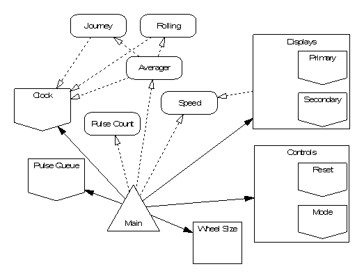
The diagram shows the provisional design to be a loop-free partial ordering as required by SPARK. State initialization does not appear to present any problems; that in boundary variables is implicitly initialized by the environment and that declared local to the main program can be initialized during the first stages of program execution. Again, the wheel size requires some consideration. It is almost certainly best to regard the wheel size state as being an initialized own variable because we want to make it an import in the main program’s annotation (to show that it affects the displayed speed). This suggests the need to set up a default wheel size during elaboration of the variable package which will be used unless a different size is programmed by the user.
It is now fairly simple to produce and analyse a package specification skeleton of the entire system. The main program annotation (excluding facilities for programming the wheel size) should be of the form:
--# global in Clock.State,
--# Pulse_Queue.State,
--# Control.State;
--# out Display.State;
--# in Wheel.Size;
--# derives Display.State
--# from Clock.State,
--# Pulse_Queue.State,
--# Control.State,
--# Wheel.Size;
Completion of the system requires only the implementation of the various type packages and variables.
10.6 Addition of Wheel Size Programming
When we add facilities to change the setting of the cycle’s wheel size we introduce an extra mode of behaviour of the controller. The controller now does two quite disjoint things: allowing programming of the wheel size and performing normal operations such as speed calculation and display. The overall annotation of the main program will be the combined flow relation for both these disjoint operations and will inevitably be less clear than that shown above; however, this problem can be greatly reduced by providing clearly separated procedures at the main program level for each separate mode of operation. The same approach was taken with the first case study at Section 7.2.3 where separate procedures were used to handle the water too-full and water too-empty conditions.
The structure of the main program will thus take the form:
with Clock, Pulse_Queue, Wheel, Control, Display;
--# inherit Clock, Pulse_Queue, Wheel, Control, Display;
--# main_program;
procedure Main
--# global in Clock.State,
--# Pulse_Queue.State,
--# Control.State;
--# out Display.State;
--# in out Wheel.Size;
--# derives Display.State
--# from Clock.State,
--# Pulse_Queue.State,
--# Wheel.Size,
--# Control.State &
--# Wheel.Size
--# from *,
--# Control.State;
is
Change_Wheel_Size : Boolean;
procedure Normal_Operation
--# global in Clock.State,
--# Pulse_Queue.State,
--# Control.State,
--# Wheel.Size;
--# out Display.State;
--# derives Display.State
--# from Clock.State,
--# Pulse_Queue.State,
--# Control.State,
--# Wheel.Size;
is
--# hide Normal_Operation;
end Normal_Operation;
procedure Program_Wheel_Size
--# global in Control.State;
--# out Display.State;
--# in out Wheel.Size;
--# derives Wheel.Size,
--# Display.State
--# from Wheel.Size,
--# Control.State;
is
--# hide Program_Wheel_Size;
end Program_Wheel_Size;
procedure Check_Program_Mode(Entered : out Boolean)
--# global in Control.State;
--# derives Entered
--# from Control.State;
is
--# hide Check_Program_Mode;
end Check_Program_Mode;
begin -- Main
loop
Check_Program_Mode(Change_Wheel_Size);
if Change_Wheel_Size then
Program_Wheel_Size;
else
Normal_Operation;
end if;
end loop;
end Main;
The annotations of procedures Normal_Operation and Program_Wheel_Size give very clear indications of their separate functions. The former’s annotation is identical to that suggested for the main program in the absence of wheel size programming and shows the wheel size to be just an input in normal operation. The annotation for Program_Wheel_Size shows that the wheel size can be altered and that it depends only on the control buttons (as we might hope). The display depends on the same inputs because we will need to show the user what wheel size he is selecting.
11 Information Flow Through Programs
The preceding case studies show:
· how the information flow through a program is revealed by SPARK’s annotations; and
· how its complexity is affected by decisions relating to the location of system state.
Information flows from data sources to data consumers mainly along the lines of strong coupling — the solid arrows on the diagrams illustrating the case studies. Where the coupling is weaker then information flows are not so significant. Taking the tiny compiler case study as an example we can see that the version using type packages at Section 9.4 has strong information flows from the source file boundary variable to the message and object code boundary variables. These flows are reflected in the main program annotation.
The addition of data flow arrowlets can make the direction of such flows clearer. For example, revisiting the example at Section 5.4.2 which copied an input stream to an output stream via a variable package queue, we have:
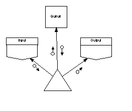
This clearly shows information flowing from the input stream, into and out of the queue variable package and to the output stream (note we have ignored, for reasons of clarity, the secondary dependencies of boundary variable streams on themselves).
As should now be clear from the case studies, making the queue an instance of a type package simplifies the flow of information thus:
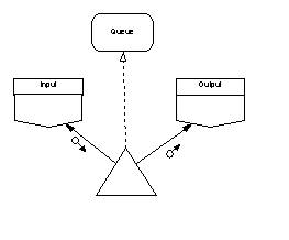
11.1 Transitivity of Strong Information Flow
An important, often overlooked, property of information flow is that it is transitive. This can be illustrated by considering a modification to the design in the previous diagram. Suppose we add a requirement to keep count of the number of times operations in the queue type package are accessed and that we choose to do so using a counter variable package which exports a suitable “Increment” operation. Superficially the design changes to the following.
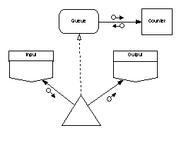
However, previously weakly coupled connections between the main program and the queue package now affect global state contained in the counter package. Coupling between the main program and the queue has therefore become strengthened by the transitive effect of the flow of information between the queue and the counter.
Care should always be taken to avoid the inadvertent introduction of strong coupling by such indirect means. Often problems can be avoided using the principles of INFORMED to locate state more effectively. In the above example we have several possibilities including:
· making the counter a type package with counters becoming a component of a queue type;
· making the counter a type package and declaring an instance of it in the main program; and
· moving call counting outside the SPARK boundary by using one of the techniques described in Appendix C.
SPARK has sometimes been seen as being concerned only with later stages in the software development lifecycle and, in particular with verification and validation of code. Some users, and critics, have wrongly seen SPARK annotations as essentially repeating information deducible from the code and therefore of little additional value.
The INFORMED approach seeks to capture system design information in annotations and use it to influence the shape and characteristics of the software implementing that system. The approach has significant benefits because it leads to a design which has known desirable properties such as loose-coupling of highly cohesive objects; such a design will consequently be “SPARK-friendly” with clear and manageable annotations.
The approach shows that, far from SPARK being unsuitable for expressing object oriented designs, a hierarchical object oriented design is likely to be the optimal solution for a SPARK system.
The exploitation of SPARK at the design stage of the life cycle facilitates a cost-efficient “correctness by construction” development method which can offer very significant advantages. In particular, code produced using the INFORMED approach is likely to be much cheaper to test and prove simpler to maintain and modify.
A Specification and Implementation of Boundary Variables
Boundary variables (see Section 3.5) provide a model of the interaction between a SPARK program and its external environment. This Appendix describes the various mechanisms and notations available in SPARK to describe such interactions and to implement boundary variable packages.
A.1 A Conceptual Model of Concurrency
As noted in Section 3.5, interactions with entities outside the boundary of the SPARK program itself are essentially concurrent. Concurrency can be modelled by providing annotations for boundary object operations which show a dependency of the input/output stream on the own variable on itself; however, the external variable form of own variable declaration, introduced with Examiner Release 6.0 is a more convenient way of expressing it.
Conceptually, for inputs, we consider the own variable of a boundary variable package to represent a sequence of all possible future input values; reading one takes the head value from the sequence and returns it thus also modifying the sequence so as to give a potentially different value when it is next inspected. For inputs the own variable can usually be considered to be initialized because when a sensor is read some value will be provided by the external device to which it is attached, it is therefore not “undefined” in the flow analysis sense. The Examiner automatically uses this model of volatile input when external variables, indicated by mode IN on their own variable declarations, are referenced.
For outputs the model is similar except that the sequence is a history of all values that have been written and each new value is appended to it. Again output streams can be considered initialized because even an empty sequence of written values is defined. More mechanically, a valve must be in some position when the system starts up even if we do no know what it is. Again, the Examiner automatically uses this model of volatile output when external variables (of mode OUT) are updated.
System boundaries must be formed by boundary variables. Because of the need to use an external own variable as a model of input/output sequences it is not possible to use type packages to provide such interfaces.
The bodies of boundary variable packages can usually be fully described in SPARK by making use of own variable refinement constituents which are themselves external variables; this is a major development over earlier versions of SPARK where such bodies usually had to be hidden.
There are essentially two different forms of boundary variable package. Simple boundary variables are those where all the state represented by an own variable of the package is made up of variables linked to the external environment and communicating in the same direction (i.e. all inputs or all outputs). Complex boundary variables are those where the package’s own variable represents a mixture of inputs and outputs or a mixture of ordinary package state variables and variables providing a link to the environment. For example:
|
No. |
Description |
Kind |
Notes |
|
1 |
Package contains a single memory-mapped variable connected to an input port and the name of the own variable is the same as the name of the memory-mapped variable. |
Simple |
All (i.e. the only) package state is an input from the environment. |
|
2 |
Package contains 3 memory-mapped variables each of which is a sensor input. Read commands exported in the package specification returns the mean of the 3 port readings. |
Simple |
All the package state variables are connected to the environment and all are inputs. A single abstract own variable can be used to represent them in the external view of the package. |
|
3 |
A package contains a memory-mapped input port and a state variable used to record the previous sensor reading. Exported read commands return the average of the current and previous reading. |
Complex |
The package state contains a mixture of variables connected to the environment and ordinary state variables. |
|
4 |
A package contains both memory-mapped output and input ports. Write commands exported in the package specification cause data to be written to the output port followed by a busy wait on the input port until an acknowledgement is received. |
Complex |
The package state contains a mixture of inputs and outputs. |
Table 3: Examples of Kinds of Boundary Variable
A.2 Simple Boundary Variable Packages
Simple boundary variable packages can make use of external own variables and external refinement constituents. These greatly simplify the description of interactions with the external environment.
A.2.1 Package Specification
For a simple input we have:
package Sensor
--# own in Stream; -- mode indicates Stream is an external variable
is
type ValueType is ...
procedure Read (Value : out ValueType);
--# global in Stream;
--# derives Value from Stream;
-- or, alternatively
function CurrentValue return ValueType;
--# global in Stream;
end Sensor;
and for an output device:
package Actuator
--# own out Stream;
is
procedure Write (Value : in ValueType);
--# global out Stream;
--# derives Stream from Value;
end Actuator;
The mode on the abstract own variable of the package marks it as an external variable. The Examiner performs analysis of external variables by considering them to be volatile so, for example, successive calls to Sensor.Read are regarded as returning potentially different values. So:
Sensor.Read (X);
Sensor.Read (Y);
--# check X = Y; -- is unprovable
A.2.2 Package Body
The simplest implementation of the Sensor package (using the version with the Read procedure) would be as follows; this is item 1 from Table 3.
package body Sensor
is
Stream : ValueType;
for Stream’Address use ... -- connection to environment
procedure Read(Value : out ValueType)
is
begin
Value := Stream;
end Read;
end Sensor;
The variable Stream, announced in the package specification, is declared and given an address clause to connect it with the environment. It is referenced in the body of procedure Read which is consistent with both its own variable mode and its global mode in the specification of procedure Read.
More usefully we can use refinement to decouple the name of the actual memory-mapped variable and the abstract name used to represent the input in the package specification. This is constistent with the INFORMED design aim of application-oriented annotations.
Using refinement in this way might give us:
package body Sensor
--# own Stream is in Port; -- one-to-one refinement
is
Port : ValueType;
for Port’Address use ...
procedure Read (Value : out ValueType)
--# global in Port;
--# derives Value from Port;
is
begin
Value := Port;
end Read;
end Sensor;
Refinement is also useful if we wish to simplify the external view of, say, a read operation by ignoring some detail about its implementation. Suppose our read operation actually read 3 memory-mapped ports and returned their mean value; this is item 2 from Table 3.
package body Sensor
--# own Stream is in Port1, in Port2, in Port3;
is
Port1,
Port2,
Port3 : ValueType;
for Port1’Address use ...
for Port2’Address use ...
for Port3’Address use ...
procedure Read (Value : out ValueType)
--# global in Port1, Port2, Port3;
--# derives Value from Port1, Port2, Port3;
is
Local1, Local2, Local3 : ValueType;
Begin
-- only simple assignments of external variables are permitted
Local1 := Port1;
Local2 := Port2;
Local3 := Port3;
-- issues such as potential overflow ignored for simplicity
Value := (Local1 + Local2 + Local3) / 3;
end Read;
end Sensor;
A.2.3 Validity Checking
The simple examples above ignore any validity checking of the input. There is no guarantee that the value read from the memory-mapped variable Port will be a valid member of the type ValueType. The Examiner will not make any assumptions about the validity of the value when generating verification conditions for the proof of exception freedom. We can strengthen the above implementation to avoid these problems thus.
SPARK 95
package body Sensor
--# own Stream is in Port;
is
Port : ValueType;
for Port’Address use ...
procedure Read (Value : out ValueType)
--# global in Port;
--# derives Value from Port;
is
Local : ValueType;
begin
Local := Port; -- no constraint check because subtypes are same
if Local'Valid then
Value := Local;
else
-- return some default value
Value := ValueType'First;
end if;
end Read;
end Sensor;
SPARK 83
package body Sensor
--# own Stream is in Port;
is
type Word is range 0 .. 65535;
-- type chosen so that any bit pattern is a valid value
Port : Word;
for Port use at ...
procedure Read (Value : out ValueType)
--# global in Port;
--# derives Value from Port;
is
Local : Word;
begin
Local := Port;
if Local <= Word (ValueType'Last) and
Local >= Word (ValueType'First) then
Value := ValueType (Local);
else
-- return some default value
Value := ValueType'First;
end if;
end Read;
end Sensor;
A.3 Complex Boundary Variable Packages
For more complex devices which have, perhaps, internal state as well as connections to the environment we cannot simply use an external abstract own variable to represent the state of the device. The usual approach is to use an ordinary (i.e. not external) own variable to and annotate the operations in a way that captures their volatile behaviour.
There are two common forms of such boundary variables which differ in the way read operations are provided and annotated. The simplest form exports procedures for reading or writing sensor values thus:
package Sensor
--# own Stream;
--# initializes Stream;
is
procedure Read(Value : out ValueType);
--# global in out Stream;
--# derives Value, Stream from Stream;
end Sensor;
The annotations of the Read operation capture the sequence model of input values described earlier; reading a value modifies the stream so that a different value may be returned at the next read. Note that the operation’s “side effect” on the stream means that reading operations of this form in boundary variables must be procedures not functions. Note also that we have added an explicit initializes annotation. Where external own variables are used they are deemed to be initialized by the environment; for ordinary own variables we have to explicitly state this.
A slightly different boundary variable input implementation separates the reading or polling of the stream from the returning of the value read. This is as if the poll operation removes the head of the sequence of input values and stores it locally. The read value can then be returned as many times as it is needed until it is changed by another poll operation. This model is useful when constructing software proofs involving input/output and is probably the preferred variant.
package Sensor
--# own Stream;
--# initializes Stream;
is
type ValueType is ...;
procedure Poll;
--# global in out Stream;
--# derives Stream from Stream;
function Read return ValueType;
--# global Stream;
end Sensor;
A.3.2 Package Body
The need to use ordinary (i.e. not external) own variables to describe complex boundary variables becomes clearer when we consider what the above abstractions are actually describing. Consider Item 3 from Table 3 above. The abstract own variable Stream has two refinement constituents: the external input port and the state variable used for smoothing purposes.
package body Sensor
--# own Stream is in Port,
--# LastValue;
is
LastValue : ValueType := 0;
Port : ValueType;
for Port’Address use ...
procedure Read (Value : out ValueType)
--# global in Port; in out LastValue;
--# derives Value from Port, LastValue &
--# LastValue from Port;
is
Local : ValueType;
begin
Local := Port;
Value := (Local + LastValue) / 2;
LastValue := Local;
end Read;
end Sensor;
Note that LastValue is initialized at declaration because it is a refinement constituent of a Stream which is an initialized own variable. Port does not have to be initialized because it is an external refinement constituent which is considered to be initialized by the external environment.
Looking at the refined derives annotation for Read we see that Value is derived from both the refinement constituents of Stream and that LastValue, which is part of Stream is obtained from Port which is also a constituent of Stream; this is completely consistent with the abstract annotation which states that Value and Stream are derived from Stream. The abstract annotation therefore captures the behaviour implemented in the package body as well as effectively modelling the volatile behaviour of calls to Read.
An example of a more complex IO device, similar to Item 4 in Table 3 can be found in [4, 5].
A.3.3 Moving Complex Devices Outside the SPARK Boundary
It may sometimes be beneficial to use an external variable in the specification of a complex boundary variable package. In such cases it will not be possible to submit the package implementation to the Examiner so, in effect, the implementation is being moved outside the SPARK boundary.
The tradeoff being made is between completeness of the analysis and the clarity of annotations involving the external device. Consider for example the case at Item 3 of Table 3 described earlier. We could decide that the fact that smoothing is taking place is an unnecessary detail as far as consumers of the Sensor package are concerned. We would like to annotate our program in terms of “smoothed temperatures”. In this case it might be reasonable to use a specification for the sensor package along the lines of that at A.3.1 which uses an external variable to represent the source of the input data. The use of an external variable simplifies the annotations of the read operation (because the “side-effect” on reading the sensor is handled by the Examiner rather than being annotated explicitly). The disadvantage is that we can no longer analyse the body of Sensor because we cannot refine an external variable onto constituents that are not external: i.e. LastValue is not a valid refinement constituent of Stream.
A.4 Obsolete Form of Simple Boundary Variable Packages
Prior to the introduction of external variables all boundary variable package specifications had to be annotated in the form described at A.3.1 since this was the only way of modelling the volatility and concurrency involved. Boundary variable package bodies were usually considered to be outside the SPARK boundary and therefore not Examined.
B Handling Secondary Design Considerations
SPARK makes a clear distinction between variables and constants; information cannot flow through constants which consequently never appear in core annotations. Sometimes, however, secondary considerations demand that data items that are logically constants (i.e. they have an unchanging value for the duration of the program’s execution) are implemented as variables. One reason might be a desire to modify the data item externally during testing; this is common in control systems such as engine controllers where a logic probe is used to modify parameters such as fuel flow gain during engine test. Such alterations would not be possible if the values were implemented as constants because the compiler might place literal values throughout the object code rather than referencing a single memory location. Variables of this kind are sometimes called “trimming variables”.
Another possible reason for using variables in place of constants might be the need to map the data to a particular location, perhaps an EEPROM board; some compilers do not allow an address clause to be placed on a constant. The EEPROM board might contain system configuration data which needs to be able to be altered without recompilation but which is logically constant in normal program operation (see for example the suggested extension to the room heater case study in Section 8).
A very effective palliative in this case is the use of parameterless functions (which also have no global annotation) in place of the trimming variables. Such parameterless functions in SPARK are syntactically and semantically indistinguishable from constants; however, their (hidden) implementations can reference and return the value of trimming variables. This allows the primary requirement of not distorting the design by introducing unnecessary variables to be reconciled with the secondary requirement of allowing trimming or configuration data to be altered without having to recompile the system.
Note that there are further design trade-offs involved here: in some cases it might be desirable to regard at least some configuration data as variables and have them appear in annotations; this would make it possible to see which system outputs depend on which configuration data.
B.2 Data logging and test points
Another common secondary requirement is the introduction of test points where the values of data and even intermediate calculations can be monitored during rig testing. The most common form of this distortion is the introduction of additional own variables which unnecessarily increase the complexity of system state and the annotations which describe it. Such variables are, in direct contrast to the trimming variables described above, write only variables. They do not need to be there at all for the core functionality of the software. Even where the variable to be monitored does have a legitimate purpose, design distortions can still occur; this usually takes the form of forcing the variable to move from a local location to a more accessible (to test tools) static location in a package. Again this move makes data which should be local into unnecessary state of the package which must appear in an own variable or refinement annotation.
Where these extra own variables are claimed to be refinement constituents of abstract own variables representing other essential state, the resulting flow relations can become very confusing. Consider for example a calibration (or normalization) package that provides an operation to calibrate a raw data value using some form of look up table represented by the abstract own variable State. The annotated signature of the calibrate operation would be:
procedure Calibrate(Raw : in T;
Calibrated : out T);
--# global in State;
--# derives Calibrated from Raw, State;
If the secondary requirement was made that the package should store the most recent calibrated value for inspection then a variable would be needed for that purpose in the package. If that variable were made a refinement constituent of State then the annotation of Calibrate would become:
--# derives Calibrated, State from Raw, State;
which is very unintuitive; why should the look up table change as a result of a calibration call?
There are several approaches to handling write-only test points effectively. Some are described in more detail in Appendix C. All have the common attributes of:
· not relocating data purely for test/inspection purposes but providing other means to make it available; and
· not mixing test points and essential state in ways that obscure the clarity of information flow relations.
Program efficiency considerations can also be a source of design distortion; usually in the form of the introduction of additional state or state components. Consider a calibration routine again.
In the case where the routine resides in a package which already contains essential state which is used for the calibration operation we might have:
procedure Calibrate(Raw : in T;
Calibrated : out T);
--# global in State;
--# derives Calibrated from Raw, State;
Suppose it was necessary to improve the performance of the calibration operation by caching recently-calibrated values; this means some additional state to represent cached values. We might be tempted to make the cache a refinement constituent of State; however, as in the case of the very similar test points example above this would again change the subprogram signature to:
procedure Calibrate(Raw : in T;
Calibrated : out T);
--# global in out State;
--# derives Calibrated, State from Raw, State;
which is very unnatural.
The situation is no better if the look up table is constant and therefore does not appear in the operation’s annotations:
procedure Calibrate(Raw : in T;
Calibrated : out T);
--# derives Calibrated from Raw;
If we wished to cache this operation completely new state is needed. If we chose simply to store the most recent value the annotation becomes:
procedure Calibrate(Raw : in T;
Calibrated : out T);
--# global in out Cache;
--# derives Calibrated, Cache from Raw, Cache;
and this change will affect all users of the Calibrate routine. Worse still, if the calibration procedure had originally been implemented as a function (which is not unreasonable since it has only one export in its original form) then the introduction of the cache creates a side effect (illegal in SPARK) causing an even bigger disruption to users of the routine.
The introduction of the cache causes two separate problems:
2 The presence and effect of the added state propagates via SPARK’s annotations.
The first of these is easy to deal with; we always have control over where state is declared. We could, for example, declare the cache elsewhere and pass it as a parameter to the calibrate operation:
procedure Calibrate(Raw : in T;
Cache : in out Caches;
Calibrated : out T);
--# derives Calibrated, Cache from Raw, Cache;
We can also avoid confusion by not making the cache a refinement constituent of an own variable representing other, essential state. By admitting the presence of the cache with an explicit own variable in addition to State we get:
procedure Calibrate(Raw : in T;
Calibrated : out T);
--# global in out Cache; in State;
--# derives Calibrated, Cache from Raw, Cache, State;
which although slightly longer makes it clear that only the cache, not the essential system state, is being affected by the calibration operation.
Although we have control over where we declare and how we annotate the state introduced by caching there are no simple palliatives to the problem of actual existence. To a large extent this is correct — the state does actually exist and it reasonable that SPARK makes us reason about its effect. Only by pushing the cache outside the SPARK boundary can we hide its presence completely; this can be achieved by judicious use of hide leaving a calibrate operation that has the external appearance of deriving calibrated values only from raw values even though its hidden internal behaviour depends on a cache variable. Note that this approach also allows the calibration routine to be a function since its illegal side effect will also occur only in hidden code.
C Techniques for Handling “Test Points”
Test points can be declared as package own variables; this is simple but has the disadvantage that they will appear in annotations. If this solution is adopted it is vital that test points are not mixed with other, essential state using SPARK refinement; this will result in confusing annotations such as those on the second example of Calibrate at Section B.2. Making the test point variable explicit (and choosing a naming convention that highlights which variables are test points) changes the annotation of this example to:
procedure Calibrate(Raw : in T;
Calibrated : out T);
--# global in State;
--# out MostRecentTP;
--# derives Calibrated,
--# MostRecentTP from Raw, State;
Although making test points explicit slightly lengthens annotations it avoids confusing effects such as the apparent change to State when a calibration is performed as shown in Section B.2.
Making the test points explicit has two other advantages:
1 When the value of MostRecentTP is monitored on the test rig we have a very clear idea of the variables that may have influenced its value (in this case Raw and State); i.e. we know the significance of the test results we obtain.
2 We can use information flow analysis to satisfy ourselves that MostRecentTP really is a test point; if it is then nothing should ever be derived from it (except perhaps itself or other test points). If a variable important to the system is ever derived from a test point then clearly the variable is no longer “write only” and must therefore be genuine system state.
C.2 Centralized Test-points Package
There are some benefits in centralizing all test points in a single package; this makes it clear that they are peripheral or secondary to normal system operation and probably makes it easier for testers to find them.
C.2.1 Visible interface
Here the test point package lies within the SPARK boundary. An abstract own variable is used to indicate that the package is an accumulator of test point values and “put” operations are provided for each value that we might wish to store in it. The put operations are called in the places where the data to be monitored is created and causes a local copy of the value to be placed into the test points package. A package that could be used with the Calibrate procedure might be:
package TestPoint
--# own State;
--# initializes State;
is
procedure PutLastCalibratedValue(X : in T);
--# global in out State;
--# derives State from State, X;
end TestPoint;
Assuming a call to TestPoint.PutLastCalibratedValue is made in the body of Calibrate its annotations would become:
--# global in State; in out TestPoint.State;
--# derives Calibrated from Raw, State &
--# TestPoint.State from *, Raw, State;
This makes it is easy to keep separate the core behaviour of the Calibrate procedure (returning a calibrated value) and the secondary requirement of storing a copy of that value for test purposes.
C.2.2 Hidden Interface
The previous method of using a test point package can easily be extended to push the collection of test points completely outside the SPARK boundary of the system and thus removing them from annotations completely; this is particularly valuable if test point collection is required only in the early, debugging stages of a development and is not intended to be part of the delivered code. In this case we do not want test points to appear in annotations since the annotations would all have to change when data logging was removed.
To hide the collection of test data we can use a test points package that is WITHed but not inherited and is thus outside the SPARK boundary of the system. The package contains variables for all the data items that are to be logged; these can be declared directly in the package specification. In each location where a value is to be logged a local, hidden procedure is used to copy the value to the test points package. The local, hidden procedure can either access the data to be logged globally in which case it is given the annotation --# derives ; making it a null statement as far as SPARK flow analysis is concerned or via a parameter in which case it can be given the annotation --# derives null from ParamName; which also makes it a null statement.
Continuing with the calibration example, the test points package (which will not be seen by the Examiner) might take the form:
package TestPoint
is
LastCalibratedValue : T;
end TestPoint;
The body of the Calibrate procedure would take the form:
procedure Calibrate(Raw : in T;
Calibrated : out T)
is
CalibratedLocal : T;
procedure LogTestPoints
--# derives ;
is
--# hide LogTestPoints;
begin
TestPoint.LastCalibratedValue := CalibratedLocal;
end LogTestPoints;
begin
CalibratedLocal := calculate value using Raw and State...
LogTestPoints; -- copy calibrated value to test points package
Calibrated := CalibratedLocal; -- return result
end Calibrate;
The annotation of the Calibrate routine remains:
--# global State;
--# derives Calibrated from Raw, State;
making the logging of test point data completely transparent. If logging is not desired in the delivered code, the local procedure can be removed without affecting any annotations.
Note that this approach also makes it possible for the calibration routine to be implemented as a function since the side effect caused by data logging is hidden.
function Calibrate(Raw : T) return T
is
CalibratedLocal : T;
procedure LogTestPoints
--# derives ;
is
--# hide LogTestPoints;
begin
TestPoint.LastCalibratedValue := CalibratedLocal;
end LogTestPoints;
begin
CalibratedLocal := ... -- calculate value using Raw and State...
LogTestPoints; -- copy calibrated value to test points package
return CalibratedLocal;
end Calibrate;
Document Control and References
Altran Praxis Limited, 20 Manvers Street, Bath BA1 1PX, UK.
Copyright Altran Praxis Limited 2010. All rights reserved.
Issue 0.1 (20/5/98): Initial draft for internal discussion
Issue 0.2 (8/9/98): First complete draft for review
Issue 0.3 (28/10/98): After incorporation of Formal review input.
Issue 1.0 (4/1/99): After final review actions.
Issue 1.1 (26/10/01): Updated to include external variables.
Issue 2.0 (31/10/01): After reviews actions in S.P0468.79.74
Issue 3.0 (27th March 2003): Updated to new template format.
Issue 4.0 (30th May 2003): Changes to new template, final format.
Issue 4.1 (11th June 2003): Final definitive issue following review.
Issue 4.2 (6th January 2005): Update company name and re-issue.
Issue 4.3 (22nd November 2005): Line Manager change.
Issue 4.4 (29th November 2005): Updated following review S.P0468.79.90
Issue 4.5 (2nd February 2009): Modify copyright notice.
Issue 4.6 (3rd September 2009): Changed incorrect reference to a correct auto cross-reference.
Issue 4.7 (4th February 2010): Rebrand to Altran Praxis Limited
Issue 4.8 (12th October 2010): Correct references to the Examiner.
Issue 4.9 (12th September 2011): Correct references to Praxis Critical Systems
Nil.
1 High Integrity Software: The SPARK Approach to Safety and Security, John Barnes, Addison Wesley, ISBN 0-321-13616-0.
2 Functional Documentation for Computer Systems, D L Parnas and J Madey, Science of Computer Programming, October 1995.
3 Software Engineering, Ian Sommerville, Addison Wesley, ISBN: 0201427656
4 SPARK 95 - The SPADE Ada 95 Kernel (including RavenSPARK), Altran Praxis
5 SPARK - The SPADE Ada Kernel, Altran Praxis